Clamping tool for transmission shaft spline shaft fork

A spline shaft fork and clamping tooling technology, which is applied in the direction of clamping, positioning devices, manufacturing tools, etc., can solve the problems of high labor intensity, difficult management, and long product production cycle.

Active Publication Date: 2017-05-31
河南中轴福漫锻造有限公司
View PDF6 Cites 4 Cited by
  • Summary
  • Abstract
  • Description
  • Claims
  • Application Information

AI Technical Summary

Problems solved by technology

[0002] The structure of the traditional drive shaft spline shaft fork forgings used in automobiles is as follows: figure 1 As shown, including the shaft part 101 and two fork parts 102, the transmission shaft spline shaft fork forging needs to go through three processes of milling, drilling the center hole of the shaft part and drilling the center hole of the fork part. In traditional processing, The clamping of the drive shaft spline shaft fork forgings does not have special tooling for clamping and positioning. It is generally fixed by claws or chucks on the machine tool. Fixing requires multiple clamping and multiple positioning, and is operated by multiple people. It can only be completed, but it has the following disadvantages: large floor area, high labor intensity, long production cycle, difficult management, multiple clamping, multiple positioning, difficult to guarantee product accuracy, and large tolerance zone

Method used


Image

  • Clamping tool for transmission shaft spline shaft fork
  • Clamping tool for transmission shaft spline shaft fork
  • Clamping tool for transmission shaft spline shaft fork

Examples


Embodiment Construction

[0024] The specific implementation manners of the present invention will be described in detail below in conjunction with the accompanying drawings.

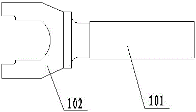
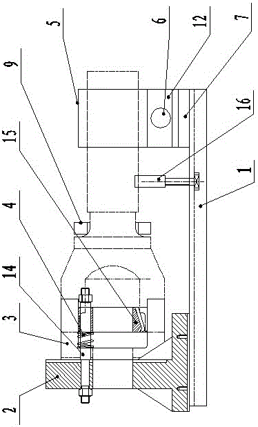
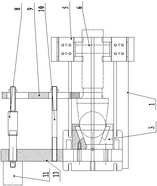
[0025] like Figure 1 to Figure 5 As shown, a clamping tool for a transmission shaft spline shaft fork according to the present invention includes a bottom plate 1, and the bottom plate 1 is respectively provided with a fork positioning mechanism and a shaft clamping mechanism from left to right, and the fork positioning mechanism There is a pressing plate mechanism between the shaft clamping mechanism, the fork positioning mechanism realizes the clamping and positioning of the fork portion 102 of the spline shaft fork of the transmission shaft, and the shaft clamping mechanism realizes the shaft portion of the spline shaft fork of the transmission shaft The clamping and positioning of 101, the pressing plate mechanism realizes the clamping and positioning of the connecting part of the shaft part 101 and the fork part 102 of the...


PUM


Abstract

The invention discloses a clamping tool for a transmission shaft spline shaft fork. The clamping tool comprises a bottom plate. The bottom plate is provided with a fork part positioning mechanism and a shaft part clamping mechanism from left to right. The fork part positioning mechanism comprises a clamp body fixedly connected with the bottom plate. Two vertically symmetrical positioning V-shaped blocks are fixedly arranged on the clamp body. A spring jacking device is arranged between the two positioning V-shaped blocks. The shaft part clamping mechanism comprises s guide rail fixedly connected with the bottom plate. Two sliding blocks are arranged on the guide rail in a matched mode. Each sliding block is provided with a clamping V-shaped block, and V-shaped notches of the clamping V-shaped blocks on the two sliding blocks are oppositely formed. A bidirectional threaded rod penetrates through the two sliding blocks in sequence. The forward thread part of the bidirectional threaded rod is in threaded connection with one of the sliding blocks, and the reverse thread part of the bidirectional threaded rod is in threaded connection with the other sliding block. According to the clamping tool for the transmission shaft spline shaft fork, clamping and positioning of the transmission shaft spline shaft fork are achieved, the clamping efficiency of the transmission shaft spline shaft fork is improved, and the product machining quality is improved.

Description

technical field [0001] The invention belongs to the technical field of transmission shaft spline shaft fork processing, and in particular relates to a clamping tool for a transmission shaft spline shaft fork. Background technique [0002] The structure of the traditional drive shaft spline shaft fork forgings used in automobiles is as follows: figure 1 As shown, including the shaft part 101 and two fork parts 102, the transmission shaft spline shaft fork forging needs to go through three processes of milling, drilling the center hole of the shaft part and drilling the center hole of the fork part. In traditional processing, The clamping of the drive shaft spline shaft fork forgings does not have special tooling for clamping and positioning. It is generally fixed by claws or chucks on the machine tool. Fixing requires multiple clamping and multiple positioning, and is operated by multiple people. It can only be completed, but it has the following disadvantages: large floor a...

Claims


Application Information

Patent Timeline
Patent Type & Authority Applications(China)
IPC IPC(8): B23Q3/08
CPCB23Q3/08
Inventor 周纯涛杨立文薛斌斌沈海波贾正锋周萍郭红想陈怡赵爱武
Owner 河南中轴福漫锻造有限公司
Why Eureka
Try Eureka