
Grinding clamp for lamp cooling fin

A heat sink and fixture technology, which is applied in the direction of grinding workpiece supports, etc., can solve the problems of not being able to meet the production and processing requirements, the harsh environment for workers to process, and the poor quality of finished products, so as to reduce labor costs and error rates, and avoid weak positioning , The effect of low manufacturing cost

Active Publication Date: 2018-04-20
GUANGDONG LXD ROBOTICS CO LTD
View PDF12 Cites 2 Cited by
  • Summary
  • Abstract
  • Description
  • Claims
  • Application Information

AI Technical Summary

Problems solved by technology

[0002] When making lamps and lanterns in industry, there is a one-step process for polishing the heat sink of lamps. At present, the traditional processing technology relies on manual feeding and grinding. The stability is poor, and it is easy to make mistakes. The quality of the processed finished products is poor and inconsistent. At the same time, the processing efficiency is slow, the production cost is high, and the processing environment of the workers is harsh. There are certain safety hazards, which cannot meet the production and processing needs.

Method used


Image

  • Grinding clamp for lamp cooling fin
  • Grinding clamp for lamp cooling fin
  • Grinding clamp for lamp cooling fin

Examples


Embodiment Construction

[0021] The present invention will be further described below in conjunction with the accompanying drawings and embodiments.

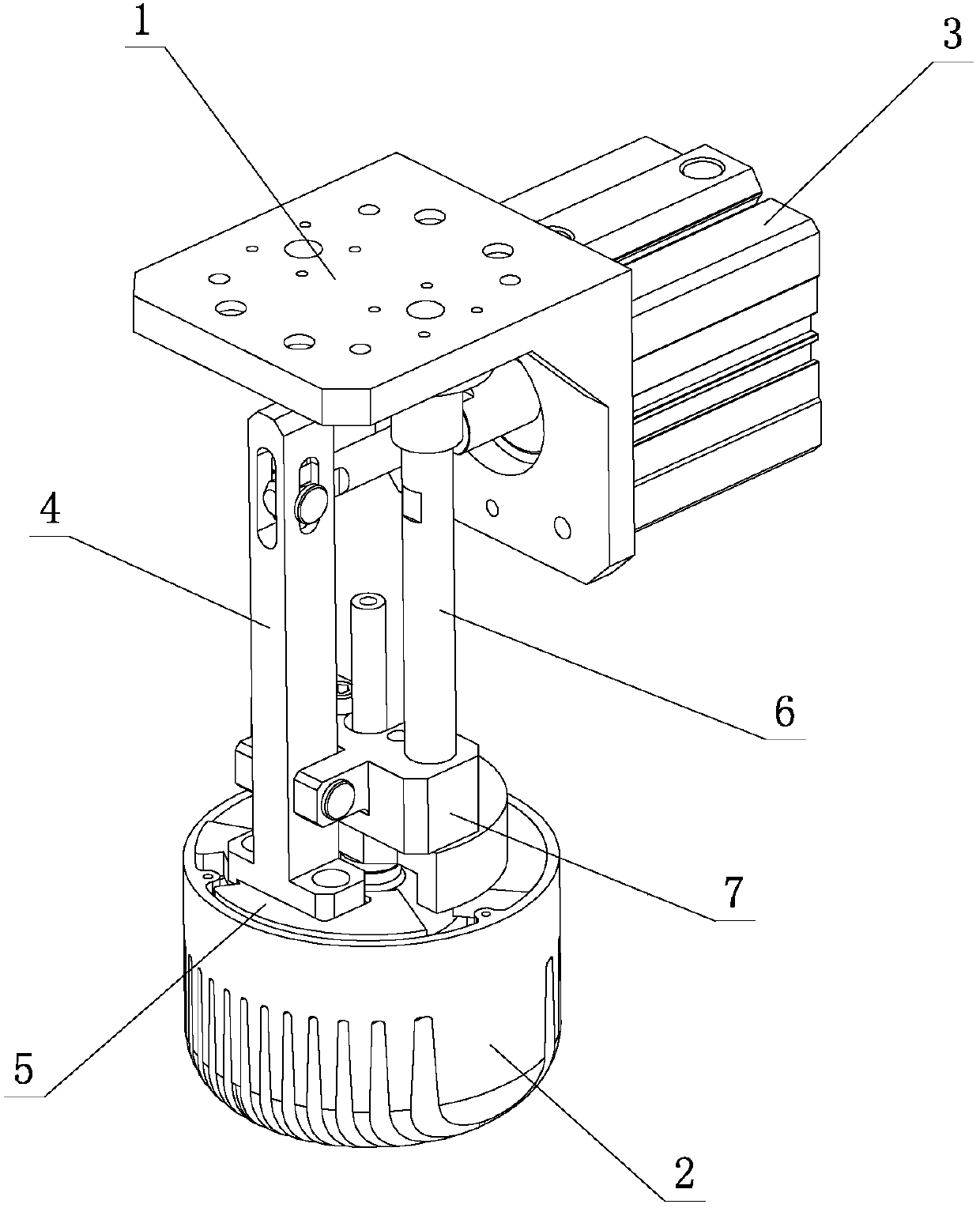
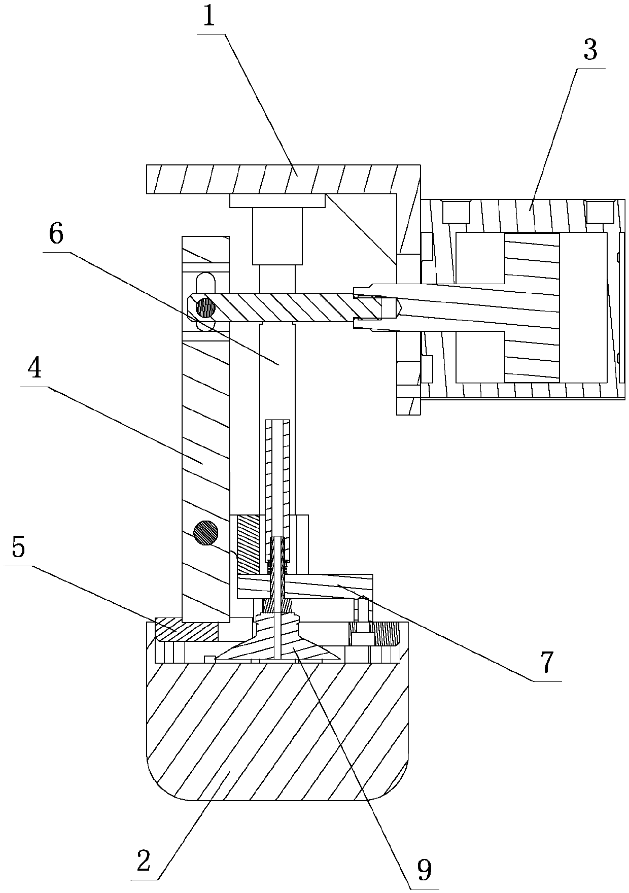
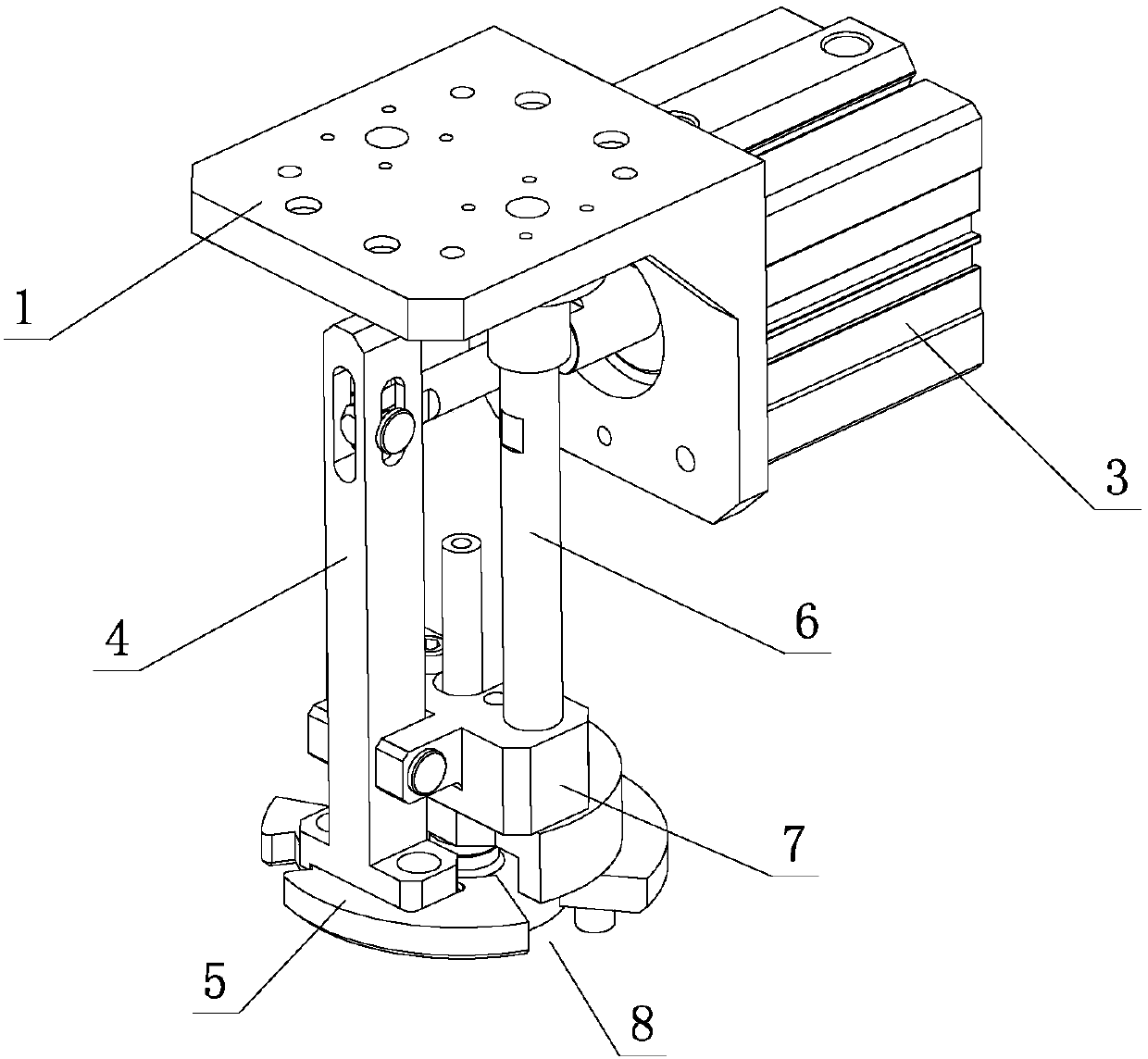
[0022] see Figure 1-Figure 4 , the grinding fixture for the heat sink of the lamp includes a fixture main body 1 and a product to be processed 2. The fixture main body 1 is provided with a power cylinder 3, a connecting rod assembly and a positioning assembly, and the power cylinder 3 is connected to the connecting rod assembly. The connecting rod assembly passes through The driving action of the power cylinder 3 is set on the fixture main body 1, and cooperates with the positioning assembly when active, so as to clamp or loosen the product 2 to be processed.

[0023] Further, the connecting rod assembly includes a connecting rod 4 and a movable part 5; wherein, one end of the connecting rod 4 is drivingly connected with the power cylinder 3, and the other end is drivingly connected with the movable part 5, and is rotatably arranged on the positioning ...


PUM


Abstract

A grinding clamp for a lamp cooling fin comprises a clamp body and a to-be-machined product. A power air cylinder, a connecting rod assembly and a positioning assembly are arranged on the clamp body.The power air cylinder and the connecting rod assembly are in driving connection. The connecting rod assembly is movably arranged on the clamp body through driving of the power air cylinder, and is matched with the positioning assembly during moving so that the to-be-machined product can be clamped or loosened. Through the above structure improvement, a movable piece is driven to swing into an empty part firstly, accordingly, the periphery size of the work position is smaller than that of the to-be-machined product, then, a suction cup is used for sucking the to-be-machined product, then, themovable piece is driven to swing to the empty part, the periphery of the work position is equivalent to the periphery size of the to-be-machined product, and accordingly, clamping and positioning of the to-be-machined product can be achieved. The grinding clamp has the beneficial effects that the structure is simple and reasonable, performance is excellent, operation is convenient, the manufacturing cost is low, production and achieving are easy, full automation and intelligence are achieved, the production efficiency is high, and safety and reliability are achieved; and practicability is high.

Description

technical field [0001] The invention relates to a grinding jig for a heat sink of a lamp. Background technique [0002] When making lamps and lanterns in industry, there is a one-step process for polishing the heat sink of lamps. At present, the traditional processing technology relies on manual feeding and grinding. The stability is poor, and it is easy to make mistakes. The quality of the processed finished products is poor and inconsistent. At the same time, the processing efficiency is slow, the production cost is high, and the processing environment for workers is harsh. There are certain safety hazards, which cannot meet the production and processing needs. Therefore, further improvement is necessary. Contents of the invention [0003] The purpose of the present invention is to provide a light fixture with simple and reasonable structure, excellent performance, convenient operation, low manufacturing cost, easy production, easy realization, full automation, intellig...

Claims


Application Information

Patent Timeline
Patent Type & Authority Applications(China)
IPC IPC(8): B24B41/06
Inventor 黄筑波蒋小双胡尕磊霍锦添
Owner GUANGDONG LXD ROBOTICS CO LTD
Learn More