
Automatic chamfering machine

A chamfering machine, automatic technology, applied in the direction of grinding frame, grinding feed motion, grinding machine parts, etc., can solve the problems of dangerous operation process, poor guarantee of processing accuracy, low processing efficiency, etc. Achieve the effect of improving work efficiency, preventing jitter, and improving chamfering accuracy

Inactive Publication Date: 2017-05-31
天津兴起工贸有限公司
View PDF5 Cites 3 Cited by
  • Summary
  • Abstract
  • Description
  • Claims
  • Application Information

AI Technical Summary

Problems solved by technology

[0002] Traditional chamfering equipment requires manual feeding and positioning, which is quite troublesome to use, and the processing efficiency is low, the processing accuracy is not guaranteed, manual feeding is required, and the operation process is dangerous. An automatic chamfering equipment is urgently needed to change the status quo

Method used

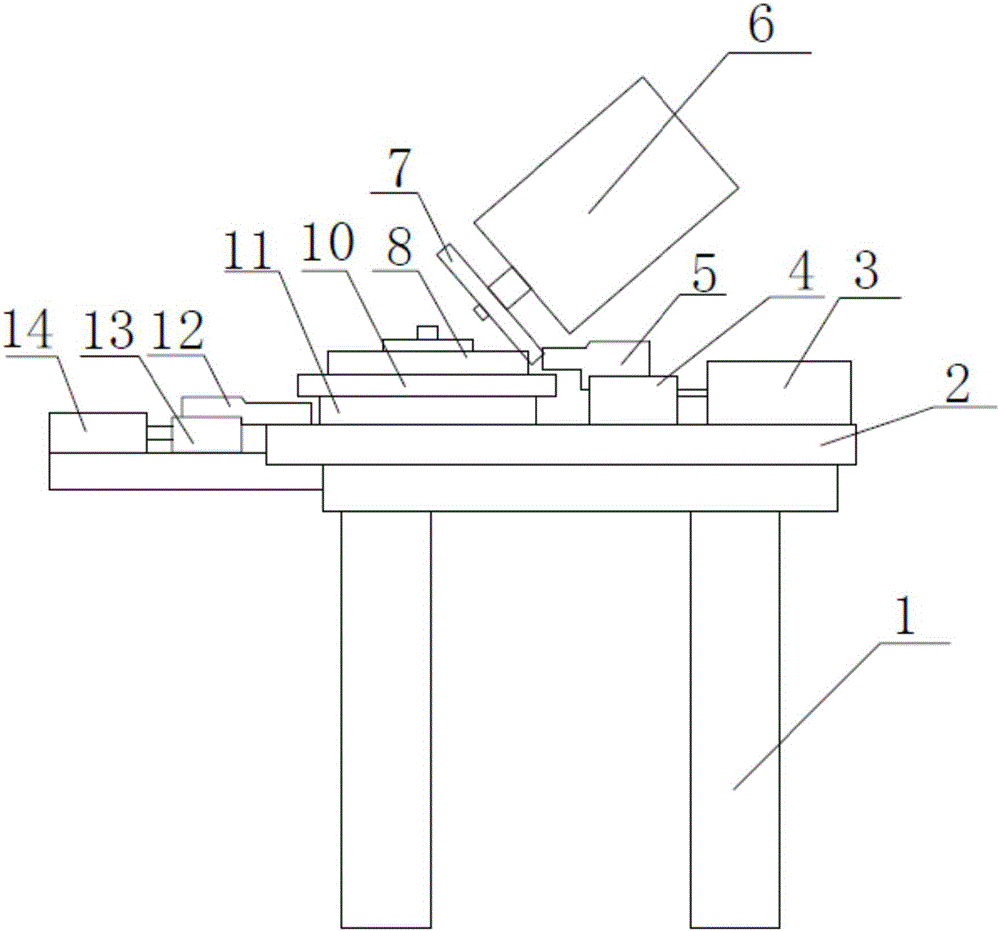
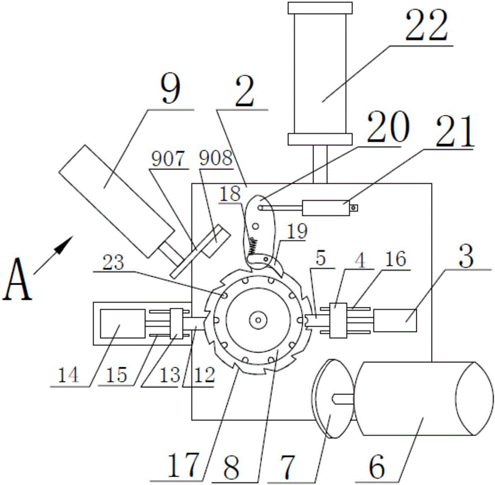
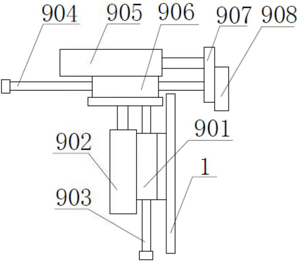

Image

  • Automatic chamfering machine
  • Automatic chamfering machine
  • Automatic chamfering machine

Examples


Embodiment Construction

[0027] It should be noted that, in the case of no conflict, the embodiments of the present invention and the features in the embodiments can be combined with each other.

[0028] In describing the present invention, it should be understood that the terms "center", "longitudinal", "transverse", "upper", "lower", "front", "rear", "left", "right", " The orientations or positional relationships indicated by "vertical", "horizontal", "top", "bottom", "inner" and "outer" are based on the orientations or positional relationships shown in the drawings, and are only for the convenience of describing the present invention and Simplified descriptions, rather than indicating or implying that the device or element referred to must have a particular orientation, be constructed and operate in a particular orientation, and thus should not be construed as limiting the invention. In addition, the terms "first", "second", etc. are used for descriptive purposes only, and should not be understood ...


PUM


Abstract

The invention provides an automatic chamfering machine. The automatic chamfering machine comprises a rack, a machining platform, a feeding rotating disc, a feeding mechanism and a chamfering mechanism. The machining platform is slidably connected to the rack, the feeding rotating disc is rotatably connected to the machining platform, and the feeding mechanism is connected to the rack. The chamfering mechanism is connected to the rack. According to the automatic chamfering machine, through the feeding mechanism, to-be-machined parts can be stacked in a workpiece machining groove of a feeding disc; and along with rotation of the feeding disc, the parts in the workpiece machining groove are sequentially machined, so that automatic-feeding machining is achieved, and work efficiency is improved. During chamfering, the feeding disc and the parts on the feeding disc are fixed, shaking of the feeding disc is prevented, and thus chamfering accuracy is improved.

Description

technical field [0001] The invention belongs to the field of mechanical processing equipment, and in particular relates to an automatic chamfering machine. Background technique [0002] Traditional chamfering equipment requires manual feeding and positioning, which is quite troublesome to use, and the processing efficiency is low, the processing accuracy is not guaranteed, manual feeding is required, and the operation process is dangerous. An automatic chamfering equipment is urgently needed to change the status quo. Contents of the invention [0003] In view of this, the present invention aims to propose an automatic chamfering machine, which can automatically load and clamp materials to complete the chamfering process. [0004] In order to achieve the above object, technical solution of the present invention is achieved in that way: [0005] An automatic chamfering machine, comprising a frame, a processing platform, a feeding turntable, a feeding mechanism, and a chamfe...

Claims


Application Information

Patent Timeline
Patent Type & Authority Applications(China)
IPC IPC(8): B24B9/00B24B41/00B24B41/02B24B41/06
CPCB24B9/00B24B41/005B24B41/02B24B41/06
Inventor 董来升
Owner 天津兴起工贸有限公司
Learn More