
Vertical variable-volume mixing barrel

A mixing drum and variable technology, applied in the direction of cement mixing equipment, clay preparation equipment, chemical instruments and methods, etc., can solve the problems of increased experimental costs, waste of materials, environmental pollution, etc., and achieve simple structure, reliable operation, and high utilization rate high effect

Inactive Publication Date: 2017-05-31
德通智能科技股份有限公司
View PDF8 Cites 1 Cited by
  • Summary
  • Abstract
  • Description
  • Claims
  • Application Information

AI Technical Summary

Problems solved by technology

Usually, various performance indicators of cement concrete are studied in the laboratory. According to different types of experiments, the amount of cement concrete required is also different. However, the volume of the mixing drum of the current mixing equipment is fixed and cannot be changed according to needs.
Therefore, when conducting experimental research on various performance indicators of cement concrete, a large amount of material waste will be caused, which will not only increase the cost of the experiment, but also cause certain pollution to the environment.

Method used


Image

  • Vertical variable-volume mixing barrel
  • Vertical variable-volume mixing barrel
  • Vertical variable-volume mixing barrel

Examples


Embodiment 1

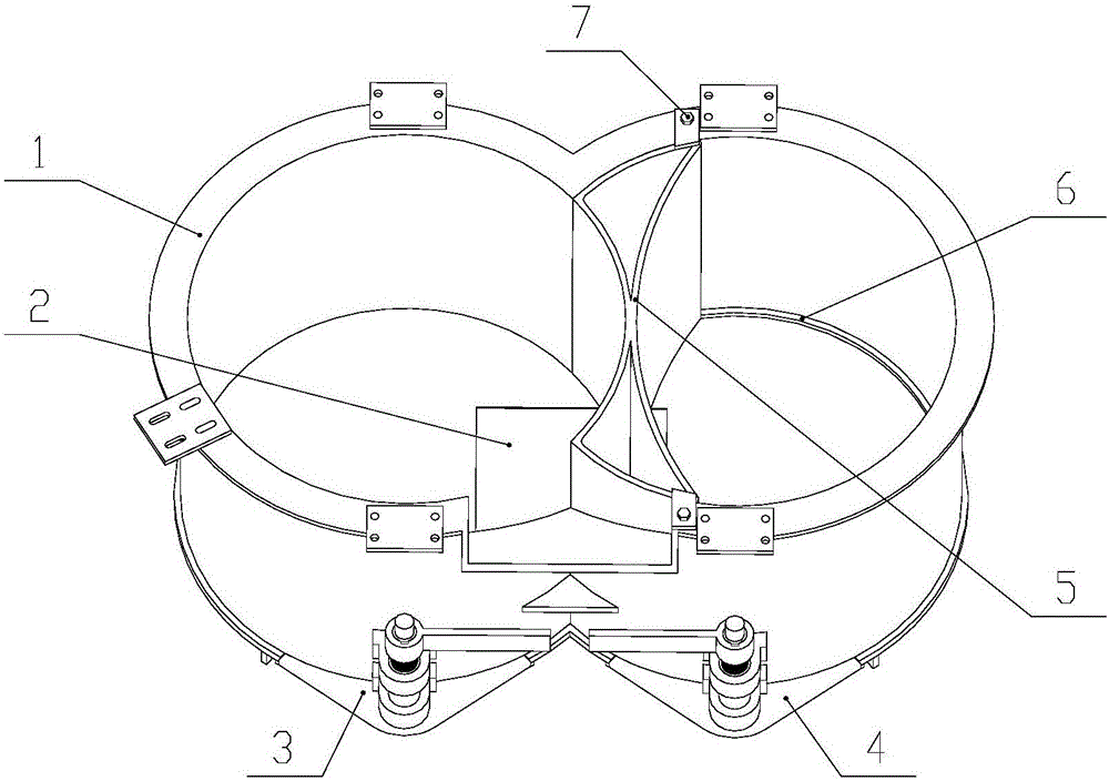
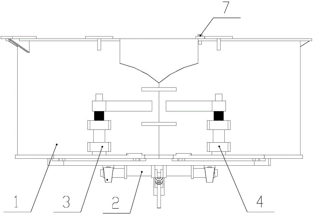
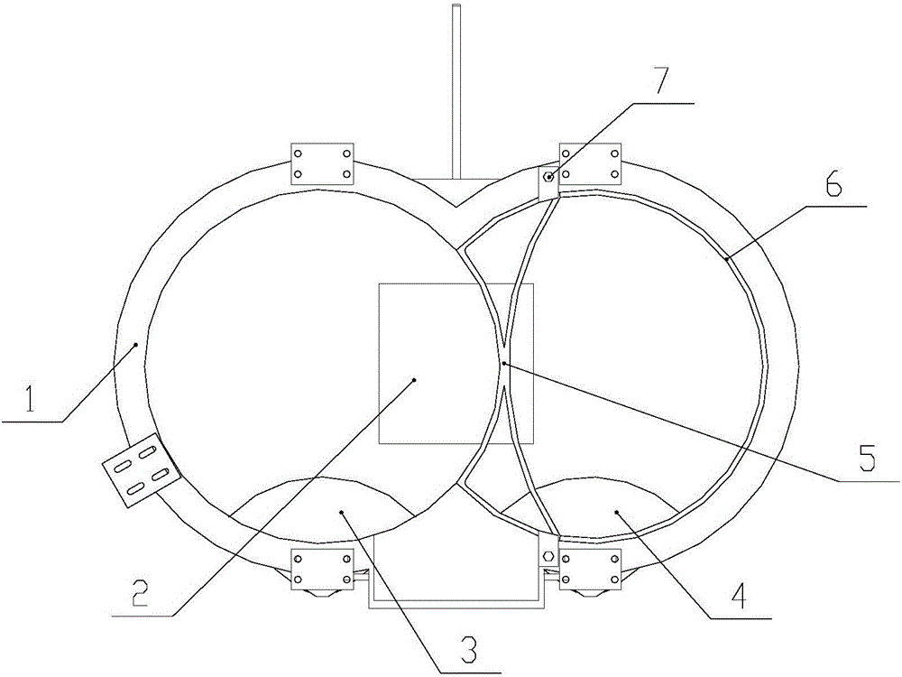
[0025] Such as Figure 4 As shown, this embodiment includes a mixing drum body 1, a left stirring device 9 and a right stirring device 8; the bottom of the mixing drum body 1 is provided with a main discharge door 2, a left discharge door 3 and a right side The discharge door 4, the main discharge door 2 is a reversing door structure controlled by a connecting rod mechanism, and the left discharge door 3 and the right discharge door 4 are both revolving door structures controlled by a handle; The side stirring device 9 and the right stirring device 8 are symmetrically installed in the left and right stirring areas of the mixing drum body 1, and the left stirring device 9 and the right stirring device 8 of the present invention are not limited to the illustrated situation.

[0026] This embodiment is a double-drum mixing condition, the mixing drum body 1 is at the maximum working volume, and its left and right mixing areas are all utilized; at this time, the material is forced ...

Embodiment 2

[0028] Such as Figure 5 As shown, this embodiment includes a mixing drum body 1, a left stirring device 9, a single cylinder partition 5 and a limit plate 6; the bottom of the mixing drum body 1 is provided with a main discharge door 2 and a left discharge door 3 and the right discharge door 4, the main discharge door 2 is a flip door structure controlled by a linkage mechanism, and the left discharge door 3 and the right discharge door 4 are revolving door structures controlled by a handle; The left stirring device 9 is installed in the left stirring area of ​​the mixing drum body 1, and the left stirring device 9 of the present invention is not limited to the situation shown in the figure.

[0029] The single-tube partition 5 is welded by an arc-shaped plate equal to the inner diameter of the mixing drum body 1, and is installed in the mixing area on the right side of the mixing drum body 1. The lower end of the single-tube partition 5 is limited by a stop plate 6 Its posi...


PUM


Abstract

The invention discloses a vertical variable-volume mixing barrel which comprises a double-barrel type mixing barrel body. A detachable single-barrel partition plate is arranged between two barrel bodies of the mixing barrel body. A main discharging door is arranged in the center of the bottom of the mixing barrel. A left discharging door and a right discharging door are arranged on one side of the bottom of the mixing barrel. According to the vertical variable-volume mixing barrel, the effective working volume of the mixing barrel can be changed, and switching of the double-barrel mixing condition and the single-barrel mixing condition can be achieved.

Description

technical field [0001] The invention belongs to the field of mixing equipment, and in particular relates to a vertical variable volume mixing drum. Background technique [0002] Cement concrete is the most widely used important building material in modern engineering construction, and the mixer is the main equipment for the production of cement concrete. It mixes different materials with a certain proportion according to the national standard to form a mixture that meets the quality requirements. Usually, various performance indicators of cement concrete are studied in the laboratory. According to different types of experiments, the amount of cement concrete required is also different. However, the volume of the mixing drum of the current mixing equipment is fixed and cannot be changed according to needs. . Therefore, when conducting experimental research on various performance indicators of cement concrete, a large amount of materials will be wasted, which will not only in...

Claims


Application Information

Patent Timeline
IPC IPC(8): B28C5/16B28C5/08
CPCB28C5/0806B28C5/0818B28C5/0862B28C5/16
Inventor 赵悟谢东张良奇李冠峰吕兴坤董晨希林亮亮王振鹏冯忠绪
Owner 德通智能科技股份有限公司
Learn More