An energy-saving electric punch and its working method

A working method and punch technology, which can be used in punching machines, manufacturing tools, presses, etc., can solve problems such as power waste, and achieve the effects of compact structure, remarkable energy saving effect and high stability in use.

Active Publication Date: 2019-02-22
江苏扬力数控机床有限公司
View PDF9 Cites 0 Cited by
  • Summary
  • Abstract
  • Description
  • Claims
  • Application Information

AI Technical Summary

Problems solved by technology

However, in the actual application of this type of technology, the driving power of the motor for the stamping stroke and the non-punching stroke (output power is zero) is exactly the same, resulting in waste of power

Method used


Image

  • An energy-saving electric punch and its working method
  • An energy-saving electric punch and its working method
  • An energy-saving electric punch and its working method

Examples


Embodiment Construction

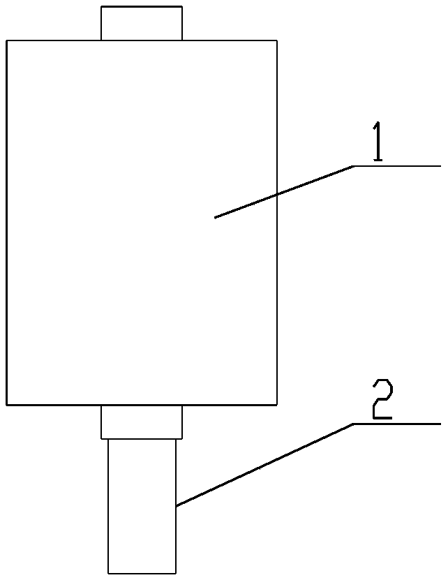
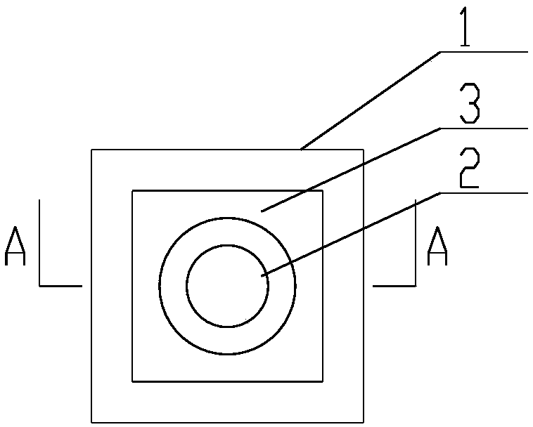
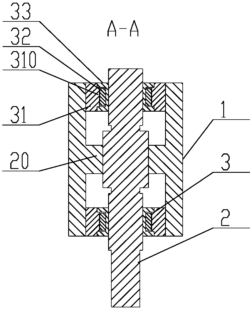
[0023] The present invention as Figure 1-7 As shown, it includes a fixed seat 1, a screw 2, a punch and a pair of drive assemblies 3, the punch is fixedly connected to the end of the screw, the screw 2 is passed through the fixed seat 1, and the screw 2 is provided with There is a guide block 20 arranged along its axial direction, the fixed seat 1 is hollow, and its inner wall is provided with a guide ring adapted to the guide block 20 along the axial direction; so that a moving pair is formed between the guide block and the guide ring ( Can only move axially, not rotate)

[0024] The surface of the screw rod 2 is provided with two sections of external threads, and the pitches can be different or equal;

[0025] The two drive assemblies 3 are connected in the fixed seat 1 and respectively sleeved on the two external threads. The drive assembly includes a stator 31, a rotor 32 and a nut 33, and the stator 31 is fixedly connected to the fixed seat 1. On the inner wall of the ...


PUM


Abstract

The invention provides an energy-saving electric plunger chip and a working method thereof and relates to the field of press machine structures. According to the energy-saving electric plunger chip and the working method thereof, the structure is exquisite, usage stability is high, service life is long, and the energy-saving effect is significant after usage. The energy-saving electric plunger chip comprises a fixed seat, a screw and a pair of driving assemblies. The screw penetrates in the fixed seat and is provided with a guide block arranged in the axial direction of the screw. The fixed seat is in a hollow shape, and a guide ring matched with the guide block is arranged on the inner wall of the fixed seat in the axial direction. The surface of the screw is provided with two segments of outer threads. The two driving assemblies are both connected in the fixed seat and are connected to the two outer threads correspondingly in a sleeving mode. Each driving assembly comprises a stator, a rotor and a nut. The energy-saving electric plunger chip and the working method thereof overall have the characteristics that the structure is exquisite, the usage stability is high, and the energy-saving effect is significant.

Description

technical field [0001] The invention relates to the field of press structure, in particular to the improvement of the electric punch therein. Background technique [0002] Traditional presses are composed of motors, flywheels, crankshafts, connecting rod mechanisms, punches and other components. While they have the advantage of large loads, they also have disadvantages such as large footprints. In this regard, those skilled in the art often use an electric punch directly driven by a motor to punch a workpiece that requires a small punching force. This type of electric punch consists of a motor, a screw, a screw seat and a punch. The motor drives the screw to rotate relative to the screw seat, and finally drives the punch to move up and down. However, in the actual application of this type of technology, the driving power of the motor for the stamping stroke and the non-press stroke (output power is zero) is exactly the same, resulting in waste of power. Contents of the in...

Claims


Application Information

Patent Timeline
Patent Type & Authority Patents(China)
IPC IPC(8): B30B15/06B30B1/18
CPCB30B1/181B30B15/065
Inventor 潘志华胡金龙陈亮
Owner 江苏扬力数控机床有限公司
Why Eureka
Try Eureka