Two-axle bogie with locking function

A bogie and functional technology, which is applied in the direction of the bogie, the device for the lateral relative movement between the chassis and the bogie, and the installation of the axle box, can solve the problem that the speed-up requirements of railway equipment rescue equipment cannot be met, and rigid side bearings cannot produce stability. Rotational friction torque, inability to effectively suppress vehicle snaking, etc., to achieve the effect of meeting the load-bearing requirements, large bearing capacity, and preventing vehicle overturning

Active Publication Date: 2018-08-31
BAOJI CSR TIMES ENG MACHINERY
View PDF8 Cites 0 Cited by
  • Summary
  • Abstract
  • Description
  • Claims
  • Application Information

AI Technical Summary

Problems solved by technology

The existing technology generally adopts rigid side bearings, and the center plate is fully loaded for traction; during the operation of the vehicle, due to the longitudinal traction force and the lateral swing of the vehicle, there will be rigid impact between the upper and lower center plates; again, due to manufacturing and installation errors, also The force between the upper and lower center plates is uneven, especially when the car body rolls sideways during operation, the upper center plate transmits the load through the edge, which may easily cause fatigue damage to the center plate
Rigid side bearings can't produce stable rotational friction torque, can't effectively suppress the snake running of the vehicle, and can't meet the speed-up requirements of railway equipment rescue equipment
On the existing high-speed vehicles, the connection form of constant contact side bearing and spherical center plate is adopted, and a locking cylinder is installed between the frame and the bogie. This structure will cause the separation of the upper and lower ball plates, and the vehicle cannot run at low speed.

Method used


Image

  • Two-axle bogie with locking function
  • Two-axle bogie with locking function
  • Two-axle bogie with locking function

Examples


Embodiment Construction

[0020] Attached below Figure 1-5 An embodiment of the present invention is described.

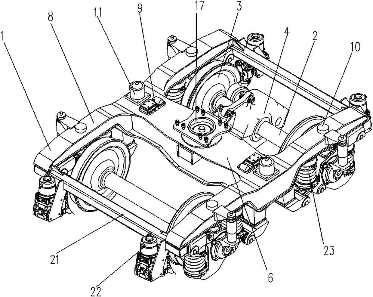
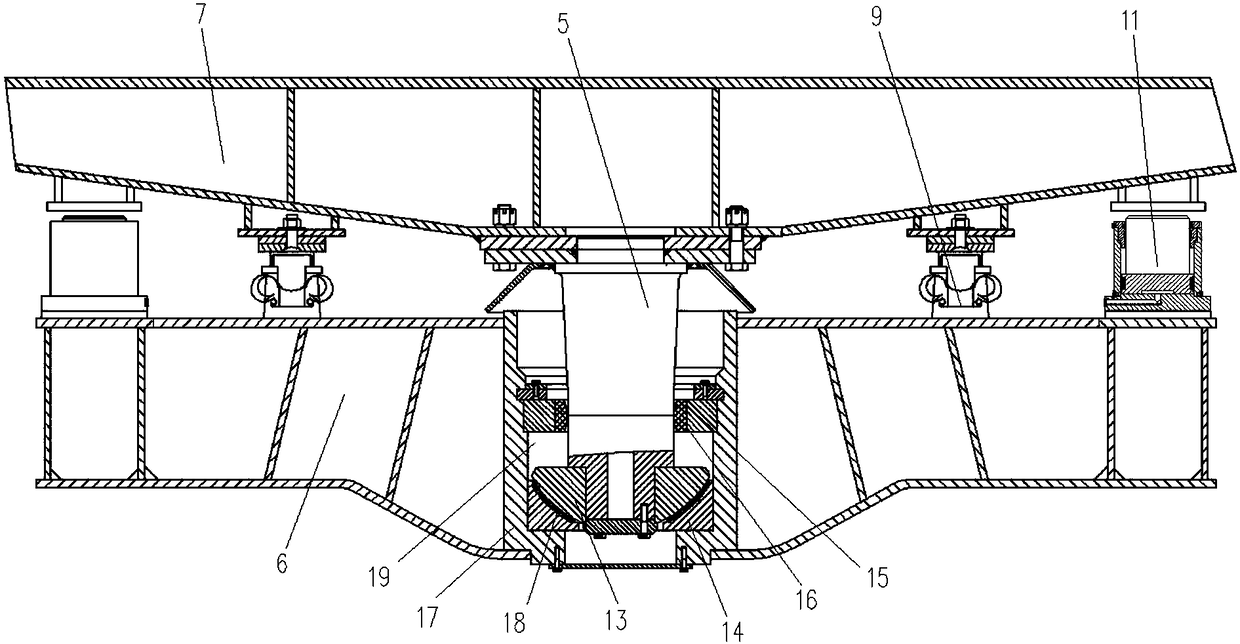
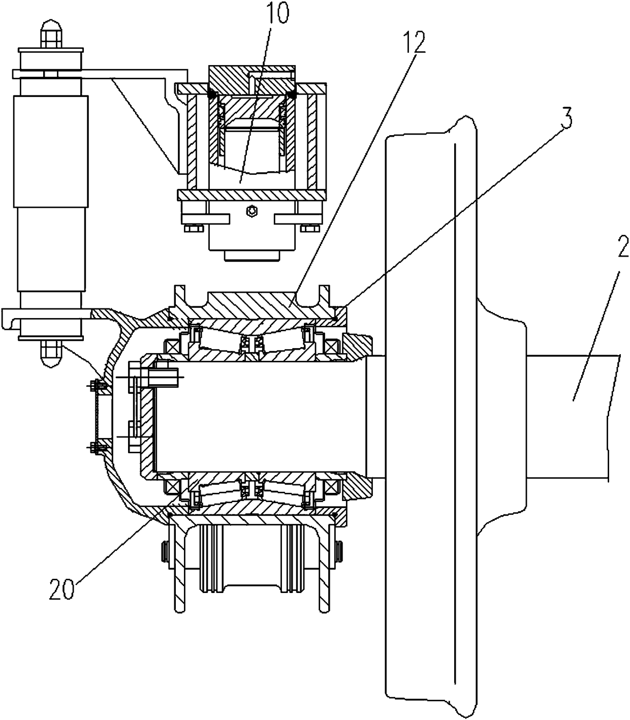
[0021] The two-axle bogie with locking function has a frame 1, an axle 2 is installed on the frame 1 and a wheel-to-axle box 3 is arranged at both ends of the axle 2, and a driving device 4 is installed on the axle 2 at one end of the frame 1, The middle part of the beam 6 of the frame 1 is provided with a central ball pin traction device and the central ball pin traction device is fixedly connected with the vehicle frame 7 above the frame 1. The contact elastic friction side bearing 9 and the constant contact elastic friction side bearing 9 are supported on the bottom of the vehicle frame 7 and cooperate with the central ball pin traction device to support the vehicle frame 7 on the top of the frame 1, and the side beam 8 of the frame 1 is provided with There is a locking device that forms a rigid support between the frame 1 and the vehicle frame 7, and between the frame 1 and the wheel-...


PUM


Abstract

The invention provides a two-axle bogie with the locking function. The bogie is provided with a framework. A center ball pin traction device is arranged in the middle of a transverse beam of the framework and fixedly connected with a frame located above the framework. A constant contact elastic friction side bearing is supported at the bottom of the frame and matched with the center ball pin traction device to support the frame above the framework, and side beams of the framework are provided with locking devices for enabling the framework and the frame to form rigid supporting and enabling the framework and a wheel set axle box to form rigid supporting. After the framework and the wheel set axle box form rigid supporting, and the framework and the frame form rigid supporting, the phenomenon that the frame swings left and right during vehicle equipment is operated is effectively avoided, the phenomenon that a vehicle tips over is avoided, the traction mode is central traction, and the requirement for low-speed walking of the vehicle is met; when the vehicle is operated at high speed, a center ball pin and the constant contact elastic friction side bearing are matched for use for spherical center plate traction, head shaking snake motion of the bogie is limited, the rolling pendulum motion of the vehicle body is limited, and the anti-dumping safety of the vehicle is promoted.

Description

technical field [0001] The invention belongs to the technical field of railway machinery design and manufacture, and in particular relates to a two-axle bogie with a locking function. Background technique [0002] With the development of my country's railway construction, various engineering vehicles and railway rescue vehicles have become necessary equipment. In the operation of engineering vehicles or rescue vehicles, due to the stability requirements of the equipment on the frame, it is necessary that there is no relative movement between the bogie wheelset and the frame, and between the frame and the frame to prevent the frame from swinging left and right and prevent the vehicle from tipping over. , and the vehicle needs to be stable when operating at low speed. The existing technology generally adopts rigid side bearings, and the center plate is fully loaded for traction; during the operation of the vehicle, due to the longitudinal traction force and the lateral swing ...

Claims


Application Information

Patent Timeline
Patent Type & Authority Patents(China)
IPC IPC(8): B61F5/14B61F5/18B61F5/24B61F5/30B61F5/32B61F5/52
CPCB61F5/14B61F5/18B61F5/24B61F5/308B61F5/32B61F5/52
Inventor 李瑞霞王秀波赵力王新虎苗武
Owner BAOJI CSR TIMES ENG MACHINERY
Why Eureka
Try Eureka