Speed reducer for road

A deceleration device and road technology, applied in roads, roads, road signs, etc., can solve the problems of vehicle brake failure and excessive speed on main roads, achieve good deceleration and enhance road safety effects

Inactive Publication Date: 2017-05-31
CHANGSHA UNIVERSITY OF SCIENCE AND TECHNOLOGY
View PDF9 Cites 0 Cited by
  • Summary
  • Abstract
  • Description
  • Claims
  • Application Information

AI Technical Summary

Problems solved by technology

By installing the above-mentioned road deceleration device on the main road (travel lane) of the long downhill section to form a stable speed lane, the downhill vehicle can maintain the speed without braking, so as to solve the problem of vehicle brake failure on the main road
The above-mentioned road deceleration device can be installed in front of the tunnel entrance to form a deceleration lane, and vehicles, especially small vehicles, can be properly decelerated to solve the problem of excessive speed at the tunnel entrance

Method used


Image

  • Speed reducer for road
  • Speed reducer for road
  • Speed reducer for road

Examples


Embodiment 1

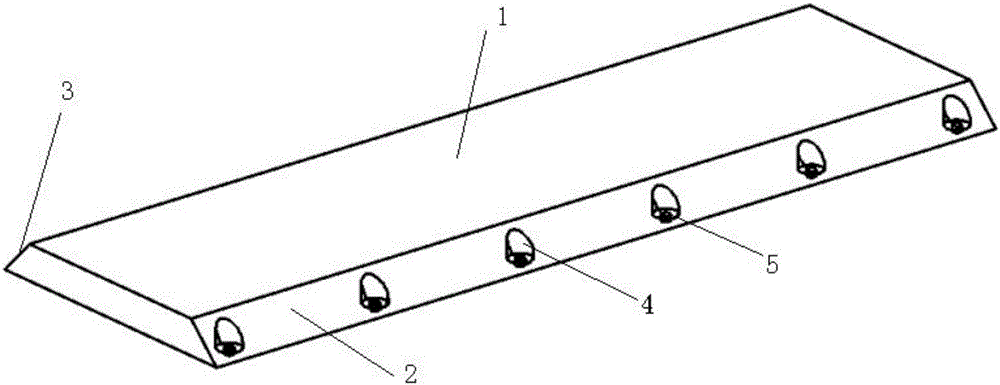
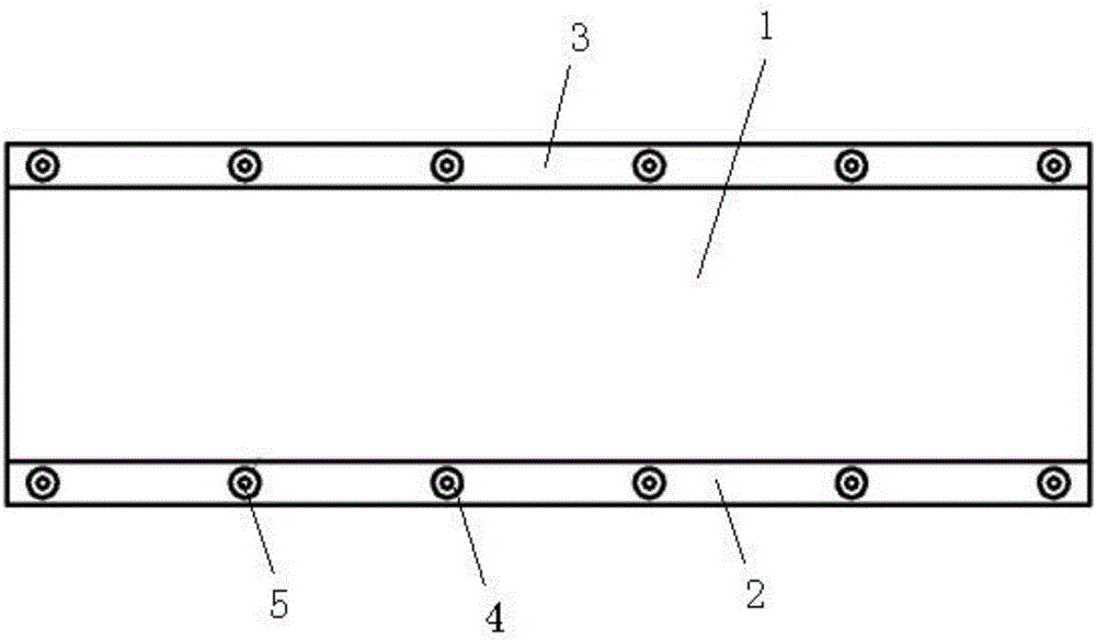
[0029] see figure 1 and figure 2 , figure 1 and figure 2 A specific embodiment of the present invention is provided, wherein, figure 1 It is a schematic diagram of the overall structure of a road deceleration device in Embodiment 1 of the present invention; figure 2 It is a top view of a road deceleration device according to Embodiment 1 of the present invention.

[0030] Such as figure 1 and figure 2 As shown, the present invention provides a road deceleration device for deceleration of vehicles on the road, including a deceleration belt body, the deceleration belt body is a rubber deceleration belt body 1 with elastic buffering effect, and the rubber deceleration belt body The setting of 1 is completely different from the rigid speed bumps of the existing speed bumps, which can effectively buffer and absorb the kinetic energy of the vehicle, thereby reducing the speed of the vehicle.

[0031] The two sides of the rubber speed bump body 1 are respectively provided ...

Embodiment 2

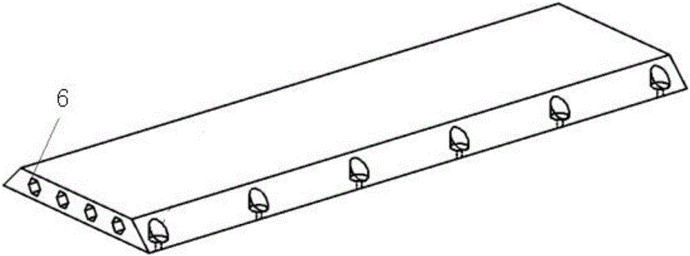
[0042] see Figure 3 to Figure 5 , Figure 3 to Figure 5 Another specific embodiment of a road deceleration device of the present invention is provided, wherein, image 3 It is a schematic diagram of the overall structure of a road deceleration device according to Embodiment 2 of the present invention; Figure 4 It is a left view of a road deceleration device according to Embodiment 2 of the present invention; Figure 5 It is a top view of a road deceleration device according to Embodiment 2 of the present invention;

[0043] In this embodiment, the rubber deceleration belt body 1 is provided with an energy absorbing through hole 6 , and the axis direction of the energy absorbing through hole 6 is parallel to the upper and lower surfaces of the rubber deceleration belt body 1 and perpendicular to the driving direction of the vehicle. The setting of the energy absorption through hole 6 can further increase the elastic deformation of the vehicle when the rubber speed bump bod...

Embodiment 3

[0051] see Figure 6 to Figure 7 , Figure 6 to Figure 7 A third specific embodiment of a road deceleration device of the present invention is provided, wherein, Figure 6 It is a schematic diagram of the overall structure of a road deceleration device according to Embodiment 3 of the present invention; Figure 7 It is a left view of a road deceleration device according to Embodiment 3 of the present invention.

[0052] The road deceleration device provided in this embodiment is suitable for installation in a tunnel section.

[0053] Compared with Embodiment 2, the road deceleration device provided in this embodiment has a larger cross-sectional area of ​​the energy absorption through hole 6, that is, the cavity provided inside the rubber deceleration belt body 1 is larger, so that the vehicle When driving on the deceleration road at the entrance of the tunnel, for vehicles with high speed, the kinetic energy will be quickly absorbed by the rubber deceleration belt body 1, ...


PUM


Abstract

The invention discloses a speed reducer for a road, which is used for speed reduction of a vehicle running on the road, particularly, speed reduction in a downhill road. The speed reducer comprises a speed bump body which is a rubber speed bump body with an elastic buffer function, wherein an upper inclination part and a lower inclination part are arranged on two sides of the rubber speed bump body respectively, the inclination direction of the upper inclination part is identical to the direction when the vehicle runs towards the rubber speed bump body, the inclination direction of the lower inclination part is identical to the direction when the vehicle runs away from the rubber speed bump body, mounting holes are formed in the upper inclination part and the lower inclination part, and connecting bolts are arranged in the mounting holes and used for fixing the rubber speed bump body on the road. The device can realize good speed reduction and control effects and enables the vehicle which is out of control during downhill driving to rapidly stop, a vehicle driving downhill to stably drive and a vehicle at a tunnel entrance to slow down, and the prominent problems that the number of conventional emergency lanes is limited, a vehicle running on a long downgrade road easily fails to brake, the speed of the vehicle at the tunnel entrance is too high and the like can be solved.

Description

technical field [0001] The present invention relates to a road traffic facility, more specifically, to a road deceleration device. Background technique [0002] Road safety, especially the driving safety on the long and downhill sections of the expressway, has always been paid attention to. However, due to the limited geographical location of the construction of escape lanes, the number of escape lanes on the long and downhill sections is limited, so that once a vehicle out of control It is difficult to be controlled if you miss the avoidance lane. In addition, because the existing avoidance lane does not have the function of avoiding danger in the true sense, but only manages to allow the out-of-control vehicle to park within a certain range, even if the out-of-control vehicle enters the avoidance lane , It is also possible that the vehicle is seriously damaged and cannot play the role of hedging. [0003] In addition, the existing avoidance lane is only a response to the ...

Claims


Application Information

Patent Timeline
Patent Type & Authority Applications(China)
IPC IPC(8): E01F9/529
Inventor 雷正保侯石静
Owner CHANGSHA UNIVERSITY OF SCIENCE AND TECHNOLOGY
Why Eureka
Try Eureka