Cast-in-place pile overfilling monitoring device and using method thereof

A monitoring device and cast-in-place pile technology, which is applied in the test of foundation structure, construction, foundation structure engineering, etc., can solve the problems of concrete waste in follow-up construction, inability to guarantee the bottom of heavy objects or bamboo poles, and large interface recognition errors, etc., to achieve guarantee The effect of control accuracy and perfusion efficiency, high use and promotion value, and reduction of material waste

Active Publication Date: 2017-05-31
JIANGSU CSSIOT TECH CO LTD
View PDF8 Cites 13 Cited by
  • Summary
  • Abstract
  • Description
  • Claims
  • Application Information

AI Technical Summary

Problems solved by technology

[0003] Although concrete pouring piles are used more and more in construction engineering, the control of the top elevation of concrete pouring piles has always been one of the difficulties in the construction of concrete pouring piles. , For example, if the amount of admixture is too high or the water consumption exceeds the standard, the concrete slump will be too large or even segregated, and laitance will appear. The strength of cast-in-place piles cannot meet the standard requirements of cast-in-place piles. Therefore, in order to avoid the influence of laitance layer, when controlling the top elevation of cast-in-place piles, it is often necessary to overfill the specified height on the set height of cast-in-place piles. Generally, cast-in-place piles need to exceed the height It is more than 500mm, and the laitance part is cut off after the concrete is solidified. Therefore, if the top elevation is set too low, the piling body finally formed by the laitance layer cannot be avoided. If the top elevation is set too high, then Cause waste of concrete and difficulties in subsequent construction (cutting away the laitance layer and the concrete exceeding the design height of the cast-in-place pile)
[0004] At present, in the process of superfill height control, the difficult problem is how to accurately identify the interface between concrete and laitance, so as to determine the actual height of concrete. The traditional construction method is to manually place heavy objects on the The design elevation position of the cast-in-situ pile or the penetrating test of the bamboo pole rely on the staff's hand feeling or experience to judge whether the heavy object has a pulling force on the human hand or whether there is concrete pushing the bamboo pole to identify the interface between the concrete and the laitance. The requirements for personnel are high, and it is impossible to ensure that the heavy objects or the bottom of the bamboo pole are accurately located at the design elevation of the cast-in-place pile, so the recognition error of the interface is relatively large. At the same time, due to the complex environment of the construction site, these methods are less affected by the site operation environment. large, which further reduces the recognition accuracy
[0005] Chinese patent CN201310141689.5 discloses an underwater cast-in-situ pile concrete overfill detector and its use method, but the device in this patent is only suitable for underwater cast-in-place piles, not completely suitable for ordinary cast-in-place piles
During the pouring process of cast-in-situ piles, the height of the concrete in the guide tube will be higher than the concrete liquid level in the pile, and the part of the concrete higher than the concrete liquid level in the pile is defined as the remaining material in the guide tube, and this part of the remaining material will further increase The height of the cast-in-place pile causes material waste
And during the pouring process, most construction companies will not do any treatment on the strength of the overfilled concrete on the top of the pile. This will undoubtedly further increase the difficulty of removing the top of the cast-in-situ pile after the pouring is completed.

Method used


Image

  • Cast-in-place pile overfilling monitoring device and using method thereof
  • Cast-in-place pile overfilling monitoring device and using method thereof

Examples


Embodiment Construction

[0033] The invention discloses a monitoring device for overfilling of cast-in-situ piles used in the process of pouring concrete and a method for using the same.

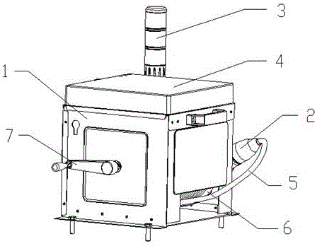
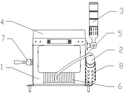
[0034] Such as Figure 1~Figure 2 Shown, a kind of cast-in-situ pile overfilling monitoring device comprises an equipment support 1, and also includes a monitoring sensor 2 for realizing real-time monitoring of the concrete filling height, and is fixedly arranged on the equipment support 1, and the monitoring sensor 2 is electrically connected to an alarm component 3 for feeding back the monitoring results of the monitoring sensor 2, and the monitoring sensor 2 is connected to the equipment bracket 1 by means of a connection component arranged on the equipment bracket 1; On the equipment bracket 1, the central control host 4 is connected with the monitoring sensor 2 and the alarm component 3 for signal transfer, and is used for signal transfer between the two.

[0035] The central control host 4 and the monitoring ...


PUM


Abstract

The invention relates to a cast-in-place pile overfilling monitoring device. The device comprises an equipment bracket, a monitoring sensor, an alarm assembly and a center control host; the monitoring sensor is used for achieving conducting real-time monitoring on a concrete spouting height; the alarm assembly is fixedly arranged on the equipment bracket, electrically connected to the monitoring sensor and used for feeding back monitoring results of the monitoring sensor; the monitoring sensor is connected to the equipment bracket with the help of a connecting assembly arranged on the equipment bracket; the center control host is fixedly arranged on the equipment bracket, in signal connection to the monitoring sensor and the alarm assembly and used for achieving signal transfer between the monitoring sensor and the alarm assembly. Through the cast-in-place pile overfilling monitoring device, the water content of different liquids can be detected through the sensor, accordingly whether concrete reaches a set scale height or not is judged, and after the concrete reaches the set scale height, an alarm is given timely. In this way, not only is the valid spouting height of a cast-in-place pile ensured, but also the overfilling amount is reduced to the greatest extent, and the subsequent chiseling and removing difficulty is lowered.

Description

technical field [0001] The invention relates to a pouring control device, in particular to a pouring pile superfill monitoring device used in the concrete pouring process and a method for using the same, belonging to the field of construction engineering. Background technique [0002] Cast-in-situ piles are formed by directly opening a circular hole with a cross-section on the designed pile position. After the hole is formed, a steel cage is added to the hole and concrete is poured. According to the hole-forming process, the cast-in-place pile can be divided into dry operation Cast-in-place piles, cast-in-place piles with mud retaining walls and artificially dug holes, etc., due to the advantages of no vibration, no soil extrusion, low noise during construction, and suitable for use in densely built urban areas, cast-in-place piles It is widely used in construction. [0003] Although concrete pouring piles are used more and more in construction engineering, the control of t...

Claims


Application Information

Patent Timeline
Patent Type & Authority Applications(China)
IPC IPC(8): E02D33/00
CPCE02D33/00E02D2600/10
Inventor 张海滨吴伟孙杰殷念念姚洪伟石亚东王鹏天戴菁菁徐士厚皮佳高鑫鹏
Owner JIANGSU CSSIOT TECH CO LTD
Why Eureka
Try Eureka