
Concrete cast-in-place pile top elevation control device and using method thereof

A control device and technology of cast-in-place piles, which are used in sheet pile wall, foundation structure test, construction, etc., can solve the problems of high operator requirements, large interface recognition errors, and inability to guarantee measuring hammers, etc., and reduce chisel removal. Difficulty, guaranteed perfusion height, and the effect of improving flexibility and applicability

Pending Publication Date: 2019-02-22
CHINA RAILWAY NO 3 GRP CO LTD +1
View PDF0 Cites 3 Cited by
  • Summary
  • Abstract
  • Description
  • Claims
  • Application Information

AI Technical Summary

Problems solved by technology

However, this method relies on the operator's feel or experience to judge whether the concrete exerts buoyancy on the measuring hammer, which has high requirements for the operator, and cannot guarantee that the measuring hammer is accurately located at the design elevation of the cast-in-place pile, so the identification error of the interface At the same time, due to the complex environment of the construction site, these methods are greatly affected by the working environment of the construction site, which further reduces the recognition accuracy

Method used


Image

  • Concrete cast-in-place pile top elevation control device and using method thereof
  • Concrete cast-in-place pile top elevation control device and using method thereof
  • Concrete cast-in-place pile top elevation control device and using method thereof

Examples


Embodiment 1

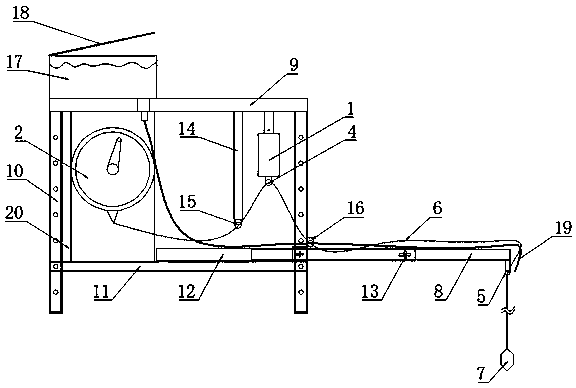
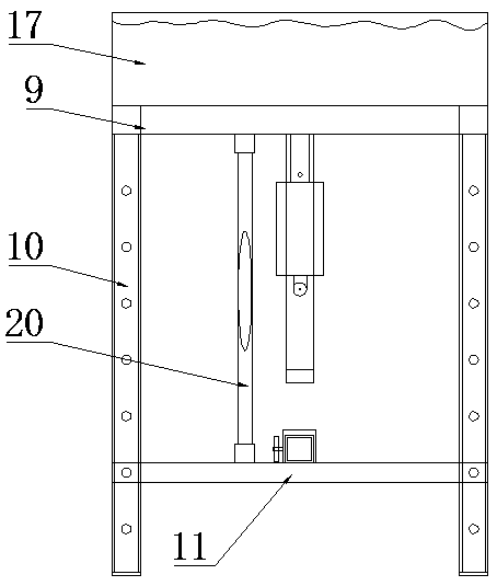
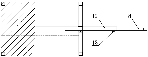
[0035] This embodiment provides a pile top elevation control device for concrete pouring piles, including a bracket, a tension sensor switch 1, a wire winder 2, a winding motor 3 that drives the wire winder 2 to rotate, a first fixed pulley 4, and a second fixed pulley 5. A scaled traction rope 6, an alarm device and a buoyancy detection hammer 7; the bracket includes a height-adjustable frame body and a horizontally telescopic and fixed horizontal cantilever 8 arranged on the frame body; the tension sensor switch 1 is used for closing the alarm The circuit where the device is located is installed on the frame with the end facing down, and the first fixed pulley 4 is installed on the end; the winding device 2 and the winding motor 3 are all installed on the frame; the second fixed slide 5 is installed on the The transverse cantilever 8 stretches out from the end of the frame body; the traction rope 6 is wound on the wire winder 2, and is drawn from the wire winder 2, passes thr...

Embodiment 2

[0057] This embodiment also provides a method for using the control device for the top elevation of concrete pouring piles, which is implemented based on the control device for the top elevation of concrete pouring piles shown in Example 1, including the following steps,

[0058] S1, hang the buoyancy detection hammer 7 on the preset elevation position of the cast-in-place pile to be processed, the tension sensor switch 1 detects that the pulling force of the buoyancy detection hammer 7 on the traction rope 6 is greater than the trigger pull, the tension sensor switch 1 is in the open state, and the alarm device is located circuit disconnected;

[0059] S2, carry out concrete pouring, until the interface between the laitance layer 101 and the concrete layer 102 is raised to the height of the buoyancy detection hammer 7, the tension sensor switch 1 is closed after reaching the trigger tension, the circuit where the alarm device is located is closed, and the alarm device sends ou...

Embodiment 3

[0064]This embodiment also provides a method for using the control device for the top elevation of concrete pouring piles, which is implemented based on the control device for the top elevation of concrete pouring piles shown in Example 1, including the following steps,

[0065] S1, hang the buoyancy detection hammer 7 on the pile opening of the cast-in-situ pile to be processed, the tension sensor switch 1 detects that the pulling force of the buoyancy detection hammer 7 on the traction rope 6 is greater than the trigger tension, the tension sensor switch 1 is in the open state, and the circuit where the alarm device is located disconnect;

[0066] S2, put the buoyancy detection hammer 7 down along the cast-in-situ pile to be processed until the buoyancy detection hammer 7 touches the bottom of the pile, the tension sensor switch 1 is closed after reaching the trigger tension, the circuit where the alarm device is located is closed, and the alarm device sends out an alarm.

...


PUM


Abstract

The invention provides a concrete pouring pile top elevation control device and a using method of the concrete cast-in-place pile top elevation control device and belongs to the technical field of building engineering. The device comprises a bracket, a tension induction switch, a winder, a winding motor, a first fixed pulley, a second fixed pulley, a traction rope with scales, an alarm device anda buoyancy detection hammer, wherein the bracket comprises a bracket body and a transverse cantilever; the tension sensing switch is installed on a frame body, and the end portion of the tension sensing switch faces downwards and is equipped with the first fixed pulley; the second fixed pulley is arranged on the end portion, extending out of the frame body, of the transverse cantilever; the traction rope is wound on the winder and led out from the winder, sequentially passes through the first fixed pulley and the second fixed pulley and is connected with the buoyancy detection hammer; and thebuoyancy detection hammer is hollow, high-density substances can be loaded or unloaded to control the quality of the buoyancy detection hammer, so that the buoyancy detection hammer can be used in different construction sites. By means of the concrete pouring pile top elevation control device and the using method of the concrete cast-in-place pile top elevation control device, an interface betweena concrete layer and a laitance layer can be identified effectively, errors caused by traditional manual measurement are avoided, and the control precision of a concrete cast-in-place pile is improved.

Description

technical field [0001] The invention relates to the technical field of construction engineering, in particular to a control device for the top elevation of concrete pouring piles and a method for using the same. Background technique [0002] The cast-in-place pile is directly drilled on the designed pile position, and its cross-section is circular. After the hole is formed, a steel cage is placed in the hole and concrete is poured. Since cast-in-situ piles have the advantages of no vibration, no soil compaction, low noise, and are suitable for use in densely built urban areas during construction, cast-in-place pile foundation engineering has been widely used in high-rise buildings, bridges, and port wharves. It has become the most important form of basic engineering in engineering construction. However, the pile top elevation control of concrete pouring piles has always been one of the difficulties in the construction of concrete pouring piles. If the fall is too large or ...

Claims


Application Information

Patent Timeline
Patent Type & Authority Applications(China)
IPC IPC(8): E02D33/00E02D5/34
CPCE02D5/34E02D33/00E02D2600/10
Inventor 胡国伟秦亮李刚柱孙伯乐唐维东曹建辉黄蒙福贾少华杨森赵昕龙毛燕超刘伟梁卿恺李晓儒曹阳屈学斌黄崇星代先斌吴磊李朝旭杨宇航高维杰李振光
Owner CHINA RAILWAY NO 3 GRP CO LTD
Learn More