Signal conversion shaft and superfill monitoring device for cast-in-situ piles using the signal conversion shaft

A signal conversion and monitoring device technology, which is applied in the test of basic structure, construction, basic structure engineering, etc., can solve the problems of waste of concrete for subsequent construction, the inability to guarantee the bottom of heavy objects or bamboo poles, and the increase in the production cost of the shaft body. The effect of control accuracy and perfusion efficiency, high usability and promotion value, and saving equipment maintenance costs

Active Publication Date: 2019-09-20
JIANGSU CSSIOT TECH CO LTD
View PDF5 Cites 0 Cited by
  • Summary
  • Abstract
  • Description
  • Claims
  • Application Information

AI Technical Summary

Problems solved by technology

[0003] Although concrete pouring piles are used more and more in construction engineering, the control of the top elevation of concrete pouring piles has always been one of the difficulties in the construction of concrete pouring piles. , For example, if the amount of admixture is too high or the water consumption exceeds the standard, the concrete slump will be too large or even segregated, and laitance will appear. The strength of cast-in-place piles cannot meet the standard requirements of cast-in-place piles. Therefore, in order to avoid the influence of laitance layer, when controlling the top elevation of cast-in-place piles, it is often necessary to overfill the specified height on the set height of cast-in-place piles. Generally, cast-in-place piles need to exceed the height It is more than 500mm, and the laitance part is cut off after the concrete is solidified. Therefore, if the top elevation is set too low, the piling body finally formed by the laitance layer cannot be avoided. If the top elevation is set too high, then Cause waste of concrete and difficulties in subsequent construction (cutting away the laitance layer and the concrete exceeding the design height of the cast-in-place pile)
[0004] At present, in the process of superfill height control, the difficult problem is how to accurately identify the interface between concrete and laitance, so as to determine the actual height of concrete. The traditional construction method is to manually place heavy objects on the The design elevation position of the cast-in-situ pile or the penetrating test of the bamboo pole rely on the staff's hand feeling or experience to judge whether the heavy object has a pulling force on the human hand or whether there is concrete pushing the bamboo pole to identify the interface between the concrete and the laitance. The requirements for personnel are high, and it is impossible to ensure that the heavy objects or the bottom of the bamboo pole are accurately located at the design elevation of the cast-in-place pile, so the recognition error of the interface is relatively large. At the same time, due to the complex environment of the construction site, these methods are less affected by the site operation environment. large, which further reduces the recognition accuracy
[0005] Chinese patent CN201310141689.5 discloses an underwater cast-in-situ pile concrete overfill detector and its use method, but the device in this patent is only suitable for underwater cast-in-place piles, not completely suitable for ordinary cast-in-place piles
Since the cable is responsible for transmitting signals during its working process, the cable needs to be connected to many electrical components. In this way, if the connecting shaft adopts a traditional shaft structure, it cannot meet the normal use requirements of the cable.
If the brush structure is adopted, the production cost of the shaft body will increase
Moreover, due to its full contact feature, the traditional brush structure has relatively large rotational friction, relies more on mechanical drive, and is prone to wear and tear, which further increases the maintenance cost of the equipment in the later period.

Method used


Image

  • Signal conversion shaft and superfill monitoring device for cast-in-situ piles using the signal conversion shaft
  • Signal conversion shaft and superfill monitoring device for cast-in-situ piles using the signal conversion shaft
  • Signal conversion shaft and superfill monitoring device for cast-in-situ piles using the signal conversion shaft

Examples


Embodiment Construction

[0029] The invention discloses a signal conversion shaft and a monitoring device for overfilling of cast-in-situ piles used in the process of pouring concrete by using the signal conversion shaft.

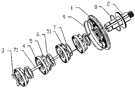
[0030] Such as figure 1 As shown, a signal conversion shaft includes a left end cover (not shown in the figure) and a right end cover 1, which is characterized in that it also includes a fixed shaft 2 that passes through the right end cover 1 and is fixedly connected with the right end cover 1, And a rotating mechanism arranged between the left end cover and the right end cover 1 and rotatably sleeved on the fixed shaft 2, the rotating mechanism is electrically connected to the fixed shaft 2, and the rotating mechanism is connected to the fixed shaft 2 An E-shaped retaining ring 3 is also arranged between the left end caps to realize tight fitting inside the rotating mechanism.

[0031] The rotating mechanism includes at least two sets of matching rotating assemblies, and each gro...


PUM


Abstract

The invention relates to a signal conversion shaft. The signal conversion shaft comprises a left end cover, a right end cover, a fixed shaft and a rotating mechanism, wherein the fixed shaft penetrates through the right end cover and is fixedly connected with the right end cover; the rotating mechanism is arranged between the left end cover and the right end cover and rotationally sleeves the fixed shaft; the rotating mechanism is electrically connected with the fixed shaft; and an E-shaped retaining ring for realizing internal matched jacking of the rotating mechanism is also arranged between the rotating mechanism and the left end cover. The invention also relates to a filling pile overfilling monitoring device. The filling pile overfilling monitoring device comprises an equipment bracket and also comprises the signal conversion shaft; and the signal conversion shaft is fixedly connected with the equipment bracket by virtue of the left end cover and the right end cover. In conclusion, the signal conversion shaft provided by the invention is delicate in design, simple in structure, good in using effect and quite high in application and popularization value.

Description

technical field [0001] The invention relates to a shaft structure and a device using the shaft structure, in particular to a signal conversion shaft and an overfilling monitoring device for cast-in-situ piles used in the concrete pouring process using the signal conversion shaft, belonging to the field of construction engineering. Background technique [0002] Cast-in-situ piles are formed by directly opening a circular hole with a cross-section on the designed pile position. After the hole is formed, a steel cage is added to the hole and concrete is poured. According to the hole-forming process, the cast-in-place pile can be divided into dry operation Cast-in-place piles, cast-in-place piles with mud retaining walls and artificially dug holes, etc., due to the advantages of no vibration, no soil extrusion, low noise during construction, and suitable for use in densely built urban areas, cast-in-place piles It is widely used in construction. [0003] Although concrete pouri...

Claims


Application Information

Patent Timeline
Patent Type & Authority Patents(China)
IPC IPC(8): E02D33/00
Inventor 张海滨吴伟
Owner JIANGSU CSSIOT TECH CO LTD
Why Eureka
Try Eureka