Concrete pouring pile pouring height control device and using method thereof

A technology for height control and cast-in-place piles, applied in measuring devices, lubrication indicating devices, liquid/fluid solids measurement, etc. Control accuracy and perfusion efficiency, small influence of human factors, and the effect of reducing the difficulty of chiseling

Active Publication Date: 2018-07-20
JIANGSU CSSIOT TECH CO LTD
View PDF7 Cites 0 Cited by
  • Summary
  • Abstract
  • Description
  • Claims
  • Application Information

AI Technical Summary

Problems solved by technology

[0003] Although concrete pouring piles are used more and more in construction engineering, the control of the top elevation of concrete pouring piles has always been one of the difficulties in the construction of concrete pouring piles. , For example, if the amount of admixture is too high or the water consumption exceeds the standard, the concrete slump will be too large or even segregated, and laitance will appear. The strength of cast-in-place piles cannot meet the standard requirements of cast-in-place piles. Therefore, in order to avoid the influence of laitance layer, when controlling the top elevation of cast-in-place piles, it is often necessary to overfill the specified height on the set height of cast-in-place piles. Generally, cast-in-place piles need to exceed the height It is more than 500mm, and the laitance part will be chiseled off after the concrete is solidified. Therefore, if the top elevation is set too low, the laitance layer cannot be avoided, and the final pile body will be unqualified. If the top elevation is set too high, It will cause waste of concrete and difficulties in subsequent construction (cutting away the laitance layer and the concrete exceeding the design height of the cast-in-place pile)
[0004] At present, in the process of controlling the superfill height, the difficult problem is how to accurately identify the interface between the concrete and the laitance, so as to determine the actual height of the concrete liquid level. The traditional construction method is to manually lift the heavy object through the measuring rope Placed at the set elevation position of the cast-in-place pile or bamboo pole penetration, rely on the staff's feel or experience to judge whether the heavy object has a pulling force on the human hand or whether there is concrete pushing the bamboo pole to identify the interface between the concrete and the laitance. The method has high requirements for the operators, and it cannot guarantee that the heavy objects or the bottom of the bamboo poles are accurately located at the set elevation position of the cast-in-place pile, so the recognition error of the interface is relatively large. At the same time, due to the complex environment of the construction site, these methods are limited The operating environment has a greater impact, which further reduces the recognition accuracy
[0005] The No. 201310141689.5 application of the China Construction Eighth Bureau No. 2 Construction Co., Ltd. on 2013-04-23 is a patent with the subject name of an underwater cast-in-situ pile concrete overfill detector and its method of use, which discloses a method for identifying laitance and concrete The interface device and method, but this device is suitable for underwater cast-in-situ piles, not completely suitable for ordinary cast-in-place piles, and this device is based on the completion of overfilling of cast-in-place piles, and then through the detector to determine whether the overfilling has exceeded Whether the height of irrigation meets the set elevation is only a confirmation and verification after over-irrigation, and the height of over-irrigation cannot be effectively controlled in advance, and the operation of this device and method is relatively complicated, which is not conducive to improving efficiency
[0006] Through further analysis, among the known detection methods, judgments are mainly made in the form of mechanical detection, and these mechanical detection methods basically rely on manual operation and are greatly affected by the external environment, so there is no one that is more accurate. Accurate and effective methods are used to solve the above problems, but most construction companies can only ensure the quality of piles by increasing the top elevation on the basis of mechanical methods, which not only wastes resources but also increases costs
[0007] In addition, according to the requirements of the construction specification, in order to ensure the quality of concrete pouring when pouring pile concrete, it is required that the guide pipe be buried in the concrete for 3-6m during pouring, and the height of the concrete in the guide pipe will be higher than The concrete liquid level in the pile, the part of the concrete that is higher than the concrete liquid level in the pile is defined as the remaining material of the feed pipe, this part of the remaining material will further increase the height of the cast-in-place pile, resulting in waste of materials, and the enterprise basically does not need to pay attention to the pile during processing. There is no treatment for the strength of the concrete poured at the top, so after the pouring is completed, it will further increase the difficulties caused by the removal of the top of the cast-in-situ pile

Method used


Image

  • Concrete pouring pile pouring height control device and using method thereof

Examples


Embodiment Construction

[0038] Objects, advantages and features of the present invention will be illustrated and explained by the following non-limiting description of preferred embodiments. These embodiments are only typical examples of applying the technical solutions of the present invention, and all technical solutions formed by adopting equivalent replacements or equivalent transformations fall within the protection scope of the present invention.

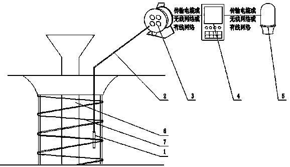
[0039] The pouring height control device for concrete pouring pile disclosed by the present invention, as attached figure 1 As shown, it includes a detection device 1 for detecting the dielectric constant or electrical conductivity of a substance, and the detection device 1 includes a counterweight casing so that it can sink into the laitance and concrete mixture by virtue of the gravity of the weight casing.

[0040] The detection device 1 can generate electromagnetic waves, and the laitance and concrete around the detection device 1 will respond to...


PUM


Abstract

The invention discloses a cast-in-place concrete pile grouting height control device and a using method thereof. The cast-in-place concrete pile grouting height control device comprises a detection device used for detecting the dielectric constants or electrical conductivity of substances, wherein the detection device is hung at a set position in a to-be-processed cast-in-place pile through a transmission cable; the transmission cable is also connected with a cable winder used for acquiring and transmitting detected signals; the cable winder communicates with a central control device used for identifying the interface of concrete and slurry according to variations of the electrical conductivity or the dielectric constants; and the central control device communicates with sound-light alarm equipment. According to the invention, the detection device is used for detecting the dielectric constants or electrical conductivity of the slurry and the concrete which arrive at the detection device, the measured data is compared with calibration parameters, and when the liquid level arriving at the detection device is determined as a concrete level, an alarm is given to remind operating personnel to stop grouting, so that the effective grouting height of the cast-in-place pile is guaranteed, the reduction of waste of grouting materials is facilitated, and the chiseling difficulty is reduced; and the whole operation process is carried out automatically and is less affected by human factor.

Description

technical field [0001] The invention relates to the field of building automation, in particular to a pouring height control device for concrete pouring piles and a method for using the same. Background technique [0002] Cast-in-situ piles are formed by directly opening a circular hole with a cross-section on the designed pile position. After the hole is formed, a steel cage is added to the hole and concrete is poured. According to the hole-forming process, the cast-in-place pile can be divided into dry operation Cast-in-place piles, cast-in-place piles with mud retaining walls and artificially dug holes, etc., due to the advantages of no vibration, no soil extrusion, low noise during construction, and suitable for use in densely built urban areas, cast-in-place piles It is widely used in construction. [0003] Although concrete pouring piles are used more and more in construction engineering, the control of the top elevation of concrete pouring piles has always been one of...

Claims


Application Information

Patent Timeline
Patent Type & Authority Patents(China)
IPC IPC(8): E02D15/04G01F23/284
CPCE02D15/04E02D2600/00G01F23/284
Inventor 张海滨孙杰王鹏天吴伟
Owner JIANGSU CSSIOT TECH CO LTD
Why Eureka
Try Eureka