Ceiling radiant tube structure embedded under reinforcing steel bars and construction method of ceiling radiant tube structure

A construction method and radiant tube technology, applied in building structure, building components, heating methods, etc., can solve problems such as difficult maintenance, high cost, and low thermal efficiency utilization rate of heat insulation and constant temperature schemes

Pending Publication Date: 2017-05-31
MOMA CHINA CO LTD
View PDF6 Cites 1 Cited by
  • Summary
  • Abstract
  • Description
  • Claims
  • Application Information

AI Technical Summary

Problems solved by technology

[0004] The embodiment of the present invention provides a ceiling radiant tube structure and its construction method based on buried steel bars, so as to

Method used


Image

  • Ceiling radiant tube structure embedded under reinforcing steel bars and construction method of ceiling radiant tube structure
  • Ceiling radiant tube structure embedded under reinforcing steel bars and construction method of ceiling radiant tube structure
  • Ceiling radiant tube structure embedded under reinforcing steel bars and construction method of ceiling radiant tube structure

Examples


Embodiment 1

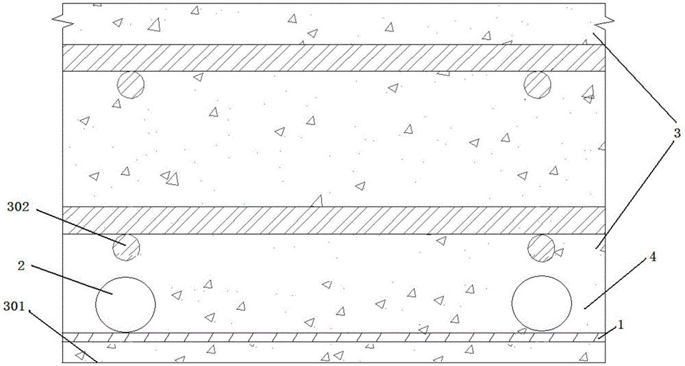
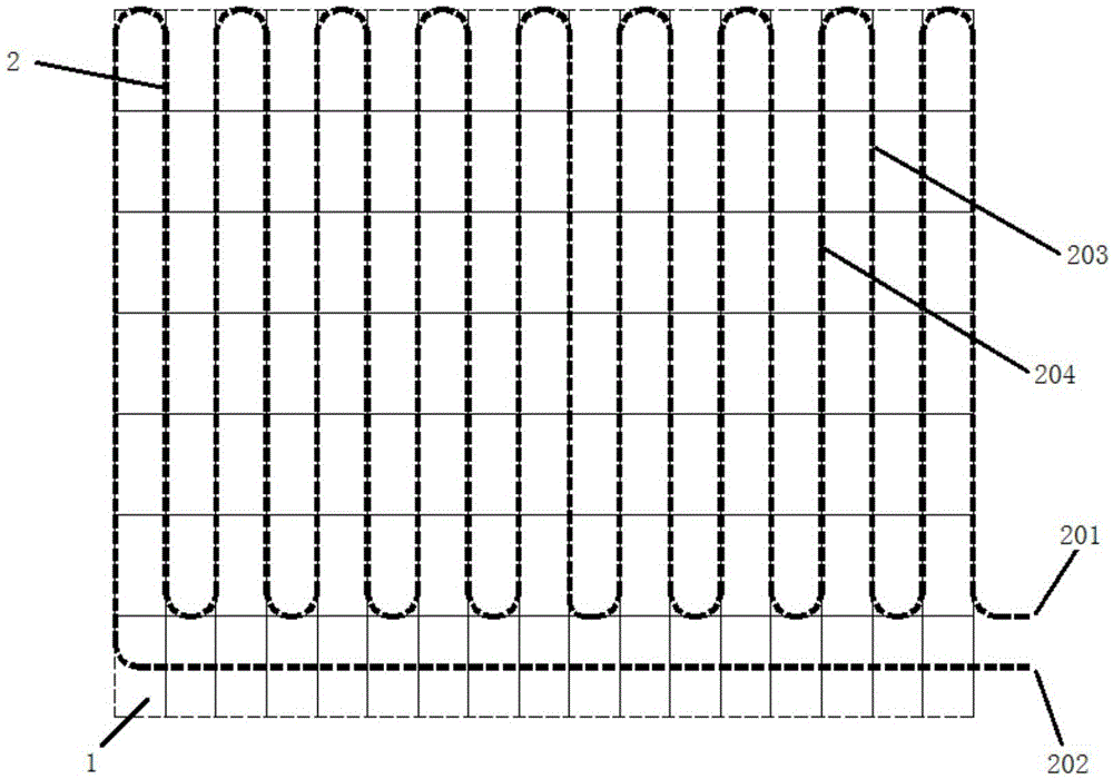
[0042] refer to figure 1 , shows a schematic structural view of a ceiling radiant tube structure based on buried steel bars in Embodiment 1 of the present invention. In this embodiment, the structure of the ceiling radiant tube based on buried steel bars may include: a steel mesh sheet 1 , an "S"-shaped ceiling radiant tube 2 , a floor 3 and a concrete layer 4 .

[0043] The ceiling radiant tube 2 is connected to the steel mesh sheet 1 through the at least one grid of the steel mesh sheet 1 . The connected steel mesh 1 and the ceiling radiant tube 2 are arranged above the bottom surface 301 of the floor, and the connected steel mesh 1 and the ceiling radiant tube 2 are connected to the bottom surface of the floor. 301 spacing is 5mm. The concrete layer 4 is filled in the gaps of the steel mesh sheet 1 , the ceiling radiant tube 2 and the bottom surface 301 of the floor slab.

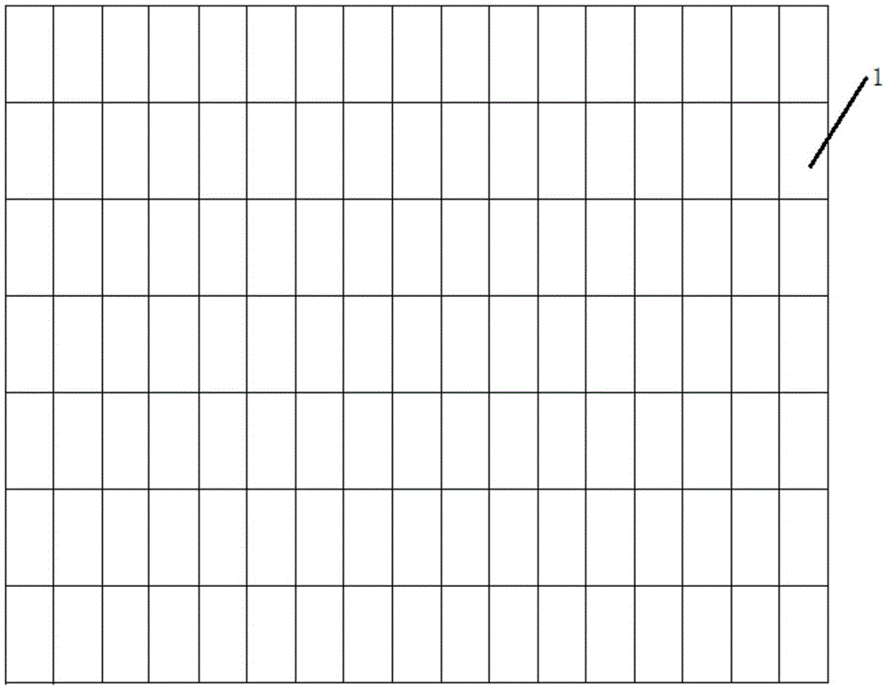
[0044] refer to figure 2 , shows a schematic structural diagram of a steel mesh sheet in Embodim...

Embodiment 2

[0049] On the basis of the first embodiment above, this embodiment also discloses a preferred ceiling radiant tube structure based on buried steel bars. The specific structure of a preferred ceiling radiant tube structure based on buried steel bars disclosed in this embodiment will be described in detail below.

[0050] refer to Figure 4 , shows a schematic structural diagram of a ceiling radiant tube structure based on buried steel bars in Embodiment 2 of the present invention. In this embodiment, the structure of the ceiling radiant tube based on buried steel bars may include: a steel mesh sheet 1 , an "S" shaped ceiling radiant tube 2 , a floor 3 and a concrete layer 4 .

[0051] The ceiling radiant tube 2 is connected to the steel mesh sheet 1 through the at least one grid of the steel mesh sheet 1 . The connected steel mesh 1 and the ceiling radiant tube 2 are arranged above the bottom surface 301 of the floor, and the connected steel mesh 1 and the ceiling radiant tub...

Embodiment 3

[0066] In combination with the above-mentioned device embodiments, this embodiment discloses the steps and procedures of a construction method based on a ceiling radiant tube structure buried under steel bars. refer to Figure 5 , shows a flow chart of steps of a construction method based on a ceiling radiant tube structure buried under steel bars in Embodiment 3 of the present invention. combined with the above Figure 1-Figure 4 , in this embodiment, the construction method of the ceiling radiant tube structure based on buried steel bars may specifically include:

[0067] Step 502, setting the reinforcement mesh sheet 1 including at least one grid.

[0068] Step 504 , connecting the "S"-shaped ceiling radiant tube 2 to the steel mesh sheet 1 through the at least one grid of the steel mesh sheet 1 .

[0069] Step 506, placing the steel mesh 1 connected with the ceiling radiant tube 2 above the bottom surface 301 of the floor, and the steel mesh 1 connected with the ceiling...


PUM

PropertyMeasurementUnit
Diameteraaaaaaaaaa

Abstract

The embodiment of the invention discloses a ceiling radiant tube structure embedded under reinforcing steel bars and a construction method of the ceiling radiant tube structure. The ceiling radiant tube structure embedded under the reinforcing steel bars comprises a reinforcing mesh, S-type ceiling radiant tubes, a floor and a concrete layer, wherein the reinforcing mesh comprises at least one grid; the ceiling radiant tubes are connected with the reinforcing mesh through the grids of the reinforcing mesh; the reinforcing mesh and the ceiling radiant tubes which are connected are arranged on the bottom face of the floor; the distance between the reinforcing mesh and the ceiling radiant tubes which are connected and the bottom face of the floor is 5 mm; and the gaps among the reinforcing mesh, the ceiling radiant tubes and the bottom face of the floor are filled with the concrete layer. Thus, the problems that a current heat insulation constant-temperature scheme is low in heat utilization efficiency, high in cost and difficult to maintain are solved.

Description

technical field [0001] The invention relates to the field of construction technology, in particular to a ceiling radiant tube structure based on buried steel bars and a construction method thereof. Background technique [0002] With the improvement of people's quality of life requirements, the standards for buildings are also constantly improving, especially for housing or office buildings. In addition to meeting the most basic strength requirements and safety requirements, they also need to meet "warm in winter and cool in summer". requirements, that is, it is necessary to achieve constant temperature control of the indoor temperature. [0003] At present, the constant temperature control of the indoor temperature is usually realized through the ceiling radiant tube. However, in the prior art, the ceiling radiant tubes are usually buried above the steel bars in the lower part of the floor. The disadvantages of this technology are: First, because the thickness of the reinfo...

Claims


Application Information

Patent Timeline
IPC IPC(8): E04B1/74E04B5/48F24D3/14
CPCF24D3/141F24D3/146E04B1/74E04B5/48
Inventor 杨帆
Owner MOMA CHINA CO LTD
Why Eureka
Try Eureka