Concrete beam or column capable of improving torsion resistance bearing capacity and construction method thereof

A technology of concrete beams and construction methods, applied in the direction of load-bearing elongated structural members, columns, pier columns, etc., to achieve the effects of improving torsional bearing capacity, ensuring stability, and improving flexural/compressive bearing capacity

Active Publication Date: 2017-05-31
徐州杉达瑞建材有限公司
View PDF6 Cites 0 Cited by
  • Summary
  • Abstract
  • Description
  • Claims
  • Application Information

AI Technical Summary

Problems solved by technology

However, there is no technical solution related to how to improve the torsional bearing capacity in concrete structures in the prior art

Method used


Image

  • Concrete beam or column capable of improving torsion resistance bearing capacity and construction method thereof
  • Concrete beam or column capable of improving torsion resistance bearing capacity and construction method thereof
  • Concrete beam or column capable of improving torsion resistance bearing capacity and construction method thereof

Examples


Embodiment 1

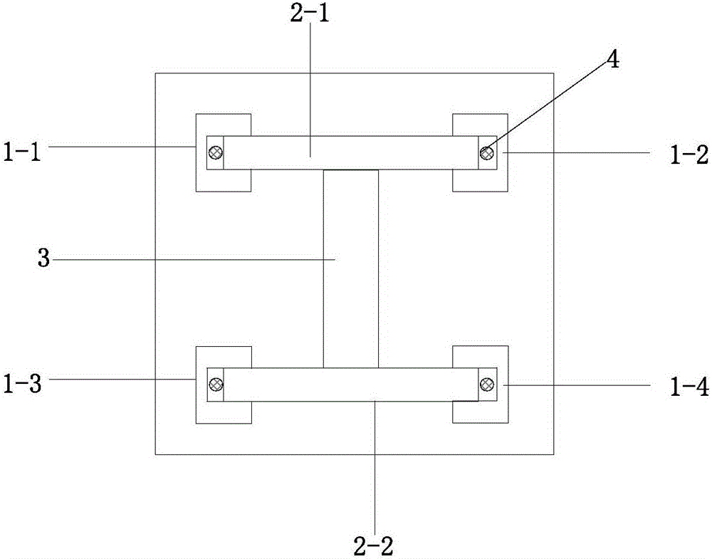
[0025] Embodiment 1: as Figure 1-2 As shown, a prefabricated concrete beam or column is embedded with steel reinforced members in the concrete beam and column, and its manufacturing method includes:

[0026] First, prepare components: steel reinforced components, which include basic steel and four U-shaped channel steels 1-1, 1-2, 1-3, and 1-4; the basic steel uses I-beam, and the upper flange 2-1, the lower flange 2-2, and the web 3, the structure of the upper flange 2-1 and the lower flange 2-2 are the same;

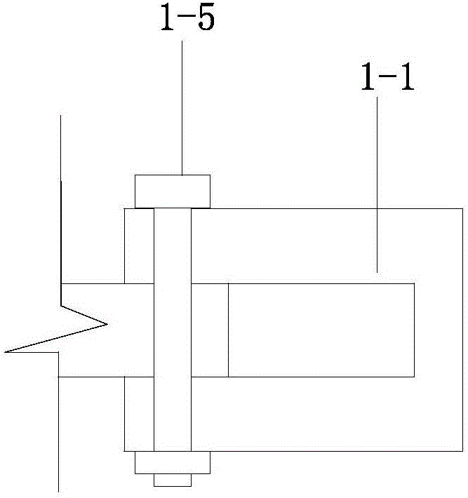
[0027] Second, insert 4 U-shaped channel steels into the four corners of the upper and lower flanges of the foundation steel. Bolt holes are preset between the U-shaped channel steel and the flanges of the foundation steel. The U-shaped channel steel and the foundation The bolt holes of the flange of the section steel are aligned, and the two are fixed by the bolt and nut assembly 1-5; there is a channel 4 through which prestressed tendons are formed between the U-sh...

Embodiment 2

[0031] Embodiment 2 is different from Embodiment 1 in that: the basic shape steel adopts "II" shape steel.

Embodiment 3

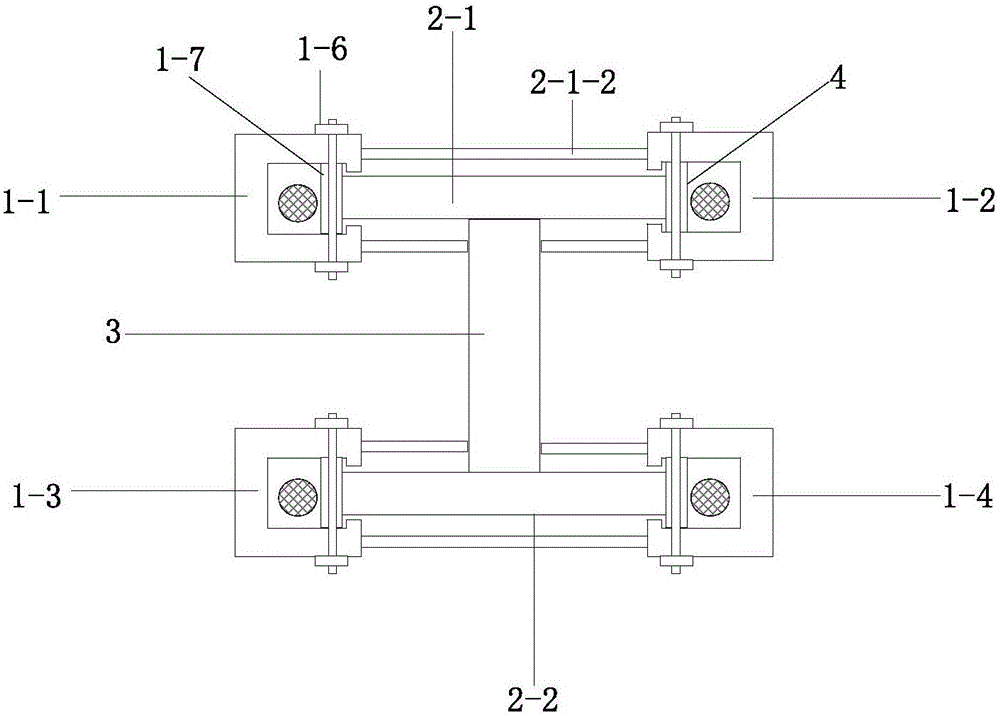
[0032] Embodiment 3: as image 3 As shown, a prefabricated concrete beam or column, the foundation steel is embedded in the beam or column, and its construction steps are as follows:

[0033] First, prepare components: shaped steel reinforced components, which include basic shaped steel and 4 U-shaped channel steels 1-1, 1-2, 1-3, 1-4; the basic shaped steel adopts I-shaped steel, and the upper flange 2- 1. Composed of lower flange 2-2 and web 3, the structure of upper flange 2-1 and lower flange 2-2 is the same; vertical Steel pipes 1-7, the two ends of the vertical steel pipe protrude from the flange, the height of the vertical steel pipe is greater than the thickness of the flange, and the vertical steel pipe is hollow; the distance between the vertical steel pipes is 15-50cm;

[0034] Second, insert 4 U-shaped channel steels into the four corners of the upper and lower flanges of the foundation steel. Bolt holes are preset between the U-shaped channel steel and the flange...


PUM


Abstract

Disclosed is a concrete beam or column capable of improving torsion resistance bearing capacity. A section steel reinforcing member is laid along the pass length direction of the longitudinal direction of the concrete beam or column. The section steel reinforcing member comprises basic section steel and U-shaped channel steel. The basic section steel comprises an upper flange, a lower flange and a web plate. The U-shaped channel steel is fixed on corners of the flanges of the basic section steel and arranged along the pass length of the basic section steel. Pore passages for penetrating prestressing tendons are formed between the U-shaped channel steel and the flanges. The prestressing tendons are arranged in the pore passages. According to the concrete beam or column capable of improving torsion resistance bearing capacity and a construction method thereof, the bending / compression resistance bearing capacity and torsion resistance bearing capacity of the beam / column can be improved simultaneously, and a good effect on reinforcing the torsion resistance bearing capacity of edge columns and edge beams of a steel structure is achieved.

Description

technical field [0001] The patent of the invention belongs to the field of construction engineering, and specifically relates to a concrete beam or column with improved torsional bearing capacity and a construction method thereof. Background technique [0002] Application number "2016100206893" discloses a prestressed assembled frame joint structure and its construction method: I-beams are pre-embedded at the end of prefabricated reinforced concrete beams, and channels are provided in the flanges and / or webs of I-beams. , the channel is used for the embedding of unbonded prestressed tendons, and the surface of the I-beam is also provided with protrusions protruding from the concrete beam; the prefabricated concrete column is provided with a steel plate on the side opposite to the beam, and the steel plate is provided with a pass-through The second channel for bonding the prestressed tendons and the jack matched with the protrusions, the positions of the second channel and th...

Claims


Application Information

Patent Timeline
Patent Type & Authority Applications(China)
IPC IPC(8): E04C3/32E04C3/34E04C3/293
CPCB28B23/022E04C3/293E04C3/32E04C3/34E04G21/00
Inventor 梁亮康忠山谷玉荣高力强李朝红高永强
Owner 徐州杉达瑞建材有限公司
Why Eureka
Try Eureka