Lock cylinder controlled self-locking anti-theft lock

An anti-theft lock and self-locking technology is applied in the field of anti-theft locks to achieve the effects of improving utilization, strong variability and high stability

Active Publication Date: 2017-05-31
重庆美心蒙迪门业制造有限公司
View PDF4 Cites 4 Cited by
  • Summary
  • Abstract
  • Description
  • Claims
  • Application Information

AI Technical Summary

Problems solved by technology

[0006] The purpose of the present invention is to solve the problem that the existing anti-theft lock can be realized by directly rotating the square pin

Method used


Image

  • Lock cylinder controlled self-locking anti-theft lock
  • Lock cylinder controlled self-locking anti-theft lock
  • Lock cylinder controlled self-locking anti-theft lock

Examples


Embodiment 1

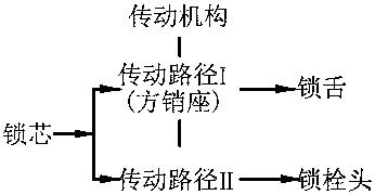
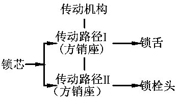
[0030] The self-locking anti-theft lock controlled by the lock cylinder of the present invention mainly includes a lock case, a lock cylinder 41, a lock bolt head, a transmission mechanism and a square pin. The transmission mechanism includes two transmission paths, and the ends of the two transmission paths are connected to the lock cylinder 41 respectively. and latch head. On the transmission path connected with the lock cylinder 41, a square pin seat 1 as a transmission hub is connected, and the square pin and the square pin seat 1 are synchronously rotated and connected.

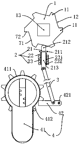
[0031] see image 3 , The self-locking anti-theft lock controlled by the lock cylinder of the present invention also includes a sliding self-locking mechanism 2, a lock cylinder toggle mechanism 4, and a connecting rod 3 that is rotatably connected with the two. In this embodiment, the sliding self-locking part 21 in the sliding self-locking mechanism 2 cooperates with the square pin seat 1 to self-lock...

Embodiment 2

[0042] The difference between this embodiment and Embodiment 1 is that in this practical example, the sliding self-locking part 21 in the sliding self-locking mechanism 2 cooperates with the square pin seat 1 to self-lock through magnetic force.

[0043] see Figure 4 , the sliding self-locking mechanism 2 includes a sliding self-locking part 21 and a guide part 23 formed with a guide track 231 . The guide piece 23 is fixedly connected in the lock housing, and the formed vertical guideway 231 points to the rotation axis of the square pin seat 1 . The sliding self-locking part 21 includes a guide hosel 213 located in the guide track 231 and a limiting head 212 protruding out of the guide track 231 .

[0044] The limiting groove 12 is provided on the square pin seat 1 , and the limiting groove 12 includes the groove bottom surface 73 in addition to the above-mentioned anti-rotation surface 71 and transfer surface 72 . The magnet 15 is embedded in the bottom surface 73 of the l...

Embodiment 3

[0050] The difference between this embodiment and Embodiment 1 and Embodiment 2 is that in this practical example, the sliding self-locking part 21 in the sliding self-locking mechanism 2 cooperates with the one-way limit rotation of the square pin seat 1 through gravity, and changes the sliding self-locking mechanism. The structural relationship between the lock piece 21 and the square pin seat 1 with one-way limited rotation. At the same time, in this embodiment, a linking rope 5 is used to replace the connecting rod 3 .

[0051] see Figure 5 , the sliding self-locking mechanism 2 includes a sliding self-locking part 21 and a guide part 23 formed with a guide track 231 . The guide piece 23 is fixedly connected in the lock housing, forming a vertical guideway 231 pointing downward to the rotation axis of the square pin seat 1 . The sliding self-locking part 21 includes a guide hosel 213 located in the guide track 231 and a limiting head 212 protruding out of the guide trac...


PUM


Abstract

The invention relates to a lock cylinder controlled self-locking anti-theft lock which comprises a locking housing, a lock cylinder and a square pin seat matched with a square pin. The lock cylinder and the square pin seat are arranged in the locking housing. The lock cylinder controlled self-locking anti-theft lock further comprises a self-locking mechanism, a lock cylinder shifting mechanism and a linkage part connected with the self-locking mechanism and the lock cylinder shifting mechanism, the self-locking mechanism is matched with the square pin seat in a one-way rotation-limiting mode, and the square pin seat rotates during locking limiting. The lock cylinder shifting mechanism with the lock cylinder transfers a rotation state of lock cylinder unlocking to the self-locking mechanism through the linkage part, and accordingly the self-locking state between the self-locking mechanism and the square pin seat is relieved. The existing problem that the anti-theft lock can be unlocked by directly turning the square pin is solved.

Description

technical field [0001] The invention relates to an anti-theft lock, in particular to a self-locking anti-theft lock controlled by a lock cylinder. Background technique [0002] There are multiple anti-theft locks on the lockset market at present. Most of the anti-theft locks include a lock cylinder, a transmission mechanism, a dead bolt and a deadbolt head. The transmission mechanism transmits and controls the dead bolt and the deadbolt head through two transmission paths respectively. see figure 1 , the control of the lock cylinder to the lock tongue and the lock bolt head is through the transmission path I and the traditional path II respectively, and there is a square pin seat for controlling the expansion and contraction of the lock bolt on the transmission path I. see figure 2 , the control of the lock cylinder to the lock tongue and the lock bolt head is through the transmission path I and the traditional path II respectively, and the transmission path I and the tra...

Claims


Application Information

Patent Timeline
Patent Type & Authority Applications(China)
IPC IPC(8): E05B15/00E05B15/04E05B47/00
CPCE05B15/0013E05B15/04E05B47/0002E05B47/0038
Inventor 夏明强
Owner 重庆美心蒙迪门业制造有限公司
Why Eureka
Try Eureka