A special maintenance ladder for power supply

A ladder frame and vertical rod technology, which is applied in the direction of ladders, overhead lines/cable equipment, buildings, etc., can solve the problems of uncontrollable lifting height, single function of maintenance ladder, and unstable high-voltage lines, etc., to improve operation safety and reduce handling The effect of labor intensity and reasonable structure

Inactive Publication Date: 2018-12-11
STATE GRID CORP OF CHINA +2
View PDF5 Cites 0 Cited by
  • Summary
  • Abstract
  • Description
  • Claims
  • Application Information

AI Technical Summary

Problems solved by technology

[0002] At present, with the continuous development of the power system, the safe power supply of the power system has been greatly challenged. In the power maintenance work, it is often necessary to use climbing ladders for climbing operations. As the tree grows, its branches are getting closer to the high-voltage line, sometimes even in contact with the high-voltage line. It is necessary to manually trim the branches of the tree to protect the high-voltage line; at the same time, the power equipment on the high-voltage line often needs to be repaired and maintained. Due to the existing The maintenance ladder has a single function and is cumbersome to use. When repairing equipment on the high-voltage line, the maintenance personnel first climb up the utility pole, then climb up the high-voltage line, and stand or lie on the high-voltage line to check and tighten the connecting nuts. However, the high-voltage line is unstable. The height cannot be controlled, often causing maintenance accidents

Method used


Image

  • A special maintenance ladder for power supply
  • A special maintenance ladder for power supply
  • A special maintenance ladder for power supply

Examples


Embodiment 1

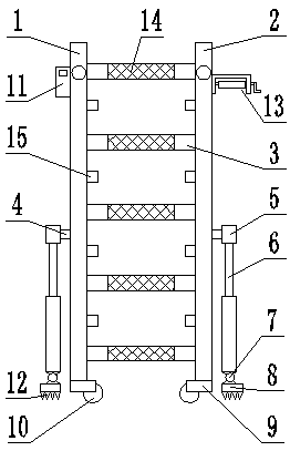
[0024] see figure 1 , Figure 4 , a schematic structural diagram of a maintenance ladder dedicated to power supply provided by an embodiment of the present invention. A maintenance ladder dedicated to power supply according to the present invention includes a ladder frame and a cross bar 3 connected to the ladder frame. The ladder frame includes a first longitudinal bar 1 And the second longitudinal bar 2, also includes two telescopic support mechanisms 6, the two telescopic support mechanisms 6 are located on the left side of the first longitudinal bar 1 and the right side of the second longitudinal bar 2, which is an adjustable support height mechanism; a fixed connection structure 4 and a right-angle sleeve 5 are provided between the upper end of the telescopic support mechanism 6 and the middle or lower side of the first longitudinal rod 1 and the second longitudinal rod 2, and the fixed connection The structure 4 is a connection structure for fixing the telescopic suppor...

Embodiment 2

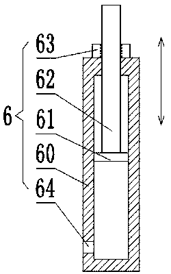
[0030]Except that telescopic support mechanism 6 cooperates with fixed connection structure 4, other structures are the same as Embodiment 1. In this embodiment, please refer to Figure 5 , provided by the embodiment of the present invention figure 1 The structural diagram of the telescopic support mechanism in , the telescopic support mechanism 6 includes a sleeve 60, and the top and bottom of the sleeve 60 are inserted with a positive threaded rod 62 and a reverse threaded rod 65 through the installation through hole, and the positive threaded rod The top of 62 is fixedly connected with the right-angle sleeve 5, the top of the reverse threaded rod 65 is hinged with the hinge 7, and the bottoms of the positive threaded rod 62 and the reversed threaded rod 65 are respectively provided with stoppers 61, the sleeve 60 A pressure relief through hole 64 is provided on the side wall of one end for discharging the gas in the sleeve 60 . The outer wall of the positively threaded rod...

Embodiment 3

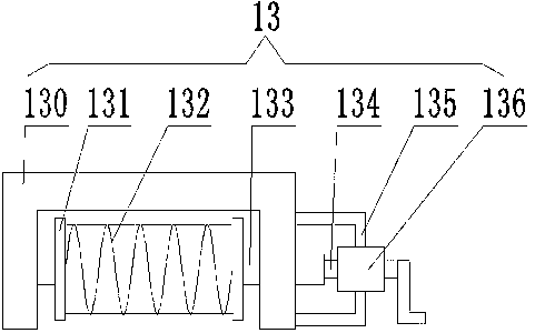
[0033] Except that telescopic support mechanism 6 cooperates with fixed connection structure 4, other structures are the same as Embodiment 1. In this embodiment, please refer to Figure 6 , provided by the embodiment of the present invention figure 1 The schematic diagram of the fixed connection structure in , the surface of the connection side of the right-angle sleeve 5 and the fixed connection structure 4 is provided with a key through hole 51, the lower end of the right-angle sleeve 5 is fixedly connected with the upper end of the telescopic support mechanism 6, and the fixed connection The structure 4 includes a key shaft 41 and a key 42 provided with key slots, and the key slots include but not limited to nine.

[0034] During use, the right-angle sleeve 5 is sleeved on the key shaft 41 provided with a keyway, and the right-angle sleeve 5 is rotated to a reasonable angle according to actual needs, and the key 42 passes through the through hole 51 of the right-angle slee...


PUM


Abstract

The invention discloses a repair ladder special for electric repair for ensuring power supply and relates to the technical field of electric power repair equipment. The repair ladder comprises a ladder rack and a plurality of cross rods connected with the ladder rack. The two sides of the ladder rack further comprise two telescopic supporting mechanisms. Twenty-four-polygonal prisms and sleeves matched with the twenty-four-polygonal prisms are arranged between the upper ends of the telescopic supporting mechanisms and the side face of the middle or the lower portion of the ladder rack. The height and the angle of the ladder rack can be controlled through cooperation of the telescopic supporting mechanisms and the sleeves, and the operation requirements under different conditions are met. The lower ends of the telescopic supporting mechanisms comprise ground nails. The bottom of the ladder rack is provided with universal wheels. In addition, the upper side of the ladder rack is provided with a lighting device and an article lifting device which can lift needed articles on the ground to the position of a user, and a serviceman does not need to get to the ground to take the needed articles. The lighting device can be used for lighting at night, and the operation safety is improved. The repair ladder is reasonable in structure and convenient to use, and the labor intensity of the serviceman is relieved.

Description

technical field [0001] The invention belongs to the technical field of electric power maintenance equipment, and in particular relates to a special maintenance ladder for power supply. Background technique [0002] At present, with the continuous development of the power system, the safe power supply of the power system has been greatly challenged. In the power maintenance work, it is often necessary to use climbing ladders for climbing operations. As the tree grows, its branches are getting closer to the high-voltage line, sometimes even in contact with the high-voltage line. It is necessary to manually trim the branches of the tree to protect the high-voltage line; at the same time, the power equipment on the high-voltage line often needs to be repaired and maintained. Due to the existing The maintenance ladder has a single function and is cumbersome to use. When repairing equipment on the high-voltage line, the maintenance personnel first climb up the utility pole, then c...

Claims


Application Information

Patent Timeline
Patent Type & Authority Patents(China)
IPC IPC(8): H02G1/02E06C7/02E06C7/00E06C7/08E06C7/42E06C7/12
CPCE06C7/00E06C7/02E06C7/08E06C7/12E06C7/42H02G1/02
Inventor 贺桂义王耀辉闫亮
Owner STATE GRID CORP OF CHINA
Why Eureka
Try Eureka