
Improved high-pressure centrifugal draught fan capable of reducing air quantity leakage

A high-pressure centrifugal fan and air volume technology, which is applied to components, mechanical equipment, machines/engines, etc. of elastic fluid pumping devices, can solve the problems of air volume leakage loss, leakage, and on-site environmental pollution, etc., to achieve small investment , reduce leakage and improve operating efficiency

Pending Publication Date: 2017-05-31
ANHUI LIUGUO CHEM CO LTD
View PDF8 Cites 1 Cited by
  • Summary
  • Abstract
  • Description
  • Claims
  • Application Information

AI Technical Summary

Problems solved by technology

The patent mentions that adding multiple fins to the rear plate of the impeller can effectively reduce the air volume leakage, but when the actual impeller is working, the air volume in the volute still has external leakage loss, especially when the fan outlet is under pressure, from Leakage in the gap between the fan shaft and the volute will be very serious, causing environmental pollution on site

Method used


Image

  • Improved high-pressure centrifugal draught fan capable of reducing air quantity leakage
  • Improved high-pressure centrifugal draught fan capable of reducing air quantity leakage
  • Improved high-pressure centrifugal draught fan capable of reducing air quantity leakage

Examples


Embodiment Construction

[0018] Now illustrate structural features of the present invention in conjunction with accompanying drawing:

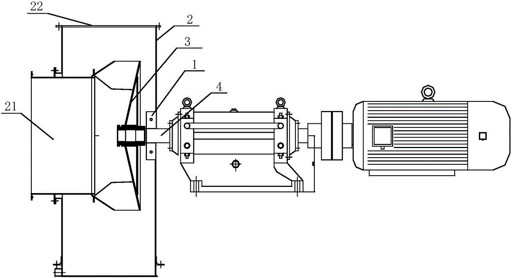
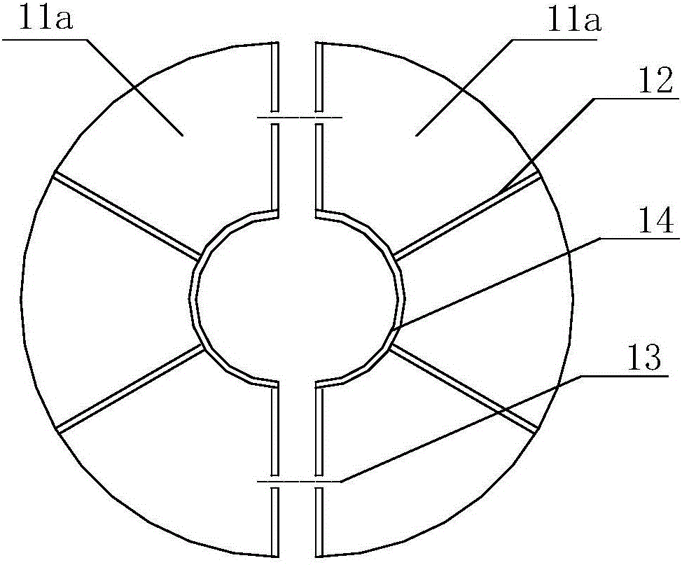
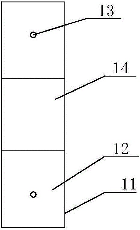
[0019] Such as figure 1 , 2 , 3, the present invention includes a volute 2, a main impeller 3 and a main shaft 4 that is transmission-connected with the main impeller 3, and an adjacent volute is installed on the main shaft 4 journal between the back of the main impeller 3 and the volute 3 The auxiliary impeller 1 arranged in the shell 2, the auxiliary impeller 1 includes an impeller chassis 11 rotating together with the main shaft 4 and a plurality of auxiliary blades 12 fixed on the impeller chassis 11 and radially distributed along the impeller chassis, the auxiliary blades 12 is located on the side of the impeller chassis 11 away from the main impeller 3, and the impeller chassis 11 is composed of two half-discs 11a that are disassembled and assembled.

[0020] The length of the auxiliary blade 12 is 1 / 2 of the diameter of the main shaft, and the width of the au...


PUM


Abstract

The invention relates to an improved high-pressure centrifugal draught fan capable of reducing air quantity leakage. The improved high-pressure centrifugal draught fan comprises a volute casing, a main impeller and a main shaft which is in transmission connection with the main impeller, wherein a secondary impeller, which is arranged nearby the volute casing, is mounted on a shaft neck of the main shaft between the back surface of the main impeller and the volute casing; the secondary impeller comprises an impeller chassis which rotates along with the main shaft and a plurality of secondary blades; the secondary blades are located at one side, far away from the main impeller, of the impeller chassis; the impeller chassis is formed by a half disc which is divided into two parts. The secondary impeller can be used for converting kinetic energy overflowed in an operation process of the main impeller of the fan into pressure energy again, so that pressure difference between a high-pressure region of an air outlet of the fan and a low-pressure region behind the main impeller is reduced, and the air quantity leakage in the volute casing can also be effectively avoided even if the air outlet of the fan is at a sultry state and the operation efficiency of the fan is improved. Furthermore, the impeller chassis has a split half disc structure and can be detached and mounted at any time; the impeller chassis can also be directly welded on the shaft neck of the main shaft and the volute casing of the fan does not need to be changed, so that the reliability and the practicability are great.

Description

technical field [0001] The invention relates to the field of high-pressure centrifugal fans, in particular to an improved high-pressure centrifugal fan capable of reducing air volume leakage. Background technique [0002] Patent CN205243937U discloses a high-pressure centrifugal fan. The high-pressure centrifugal fan is composed of an impeller, a volute, a main shaft and other components. The middle part enters and is connected with the impeller drive. The patent mentions that adding multiple fins to the rear plate of the impeller can effectively reduce the air volume leakage, but when the actual impeller is working, the air volume in the volute still has external leakage loss, especially when the fan outlet is under pressure, from Leakage in the gap between the fan shaft and the volute will be very serious, causing environmental pollution on site. Contents of the invention [0003] In order to solve the above-mentioned technical problems, the present invention provides ...

Claims


Application Information

Patent Timeline
IPC IPC(8): F04D29/28F04D29/30F04D29/62
CPCF04D29/281F04D29/30F04D29/626
Inventor 袁开宏徐景才程大伟晋勇
Owner ANHUI LIUGUO CHEM CO LTD
Learn More