Spiral separation device for hydraulic oil tank respirator

A technology of spiral separation and hydraulic oil tank, which is applied in the direction of oil supply oil tank device, fluid pressure actuation device, fluid pressure actuation system components, etc., can solve the problems of polluting the environment and affecting the appearance of the hydraulic oil tank, so as to avoid polluting the environment and exporting The effect of area reduction

Active Publication Date: 2017-05-31
扬州市杭集创意设计园有限公司
7 Cites 0 Cited by

AI-Extracted Technical Summary

Problems solved by technology

When the air in the hydraulic oil tank enters and leaves the respirator with this structure, the hydraulic oil particles contained in the air adhere to the filter cotton. When the hydraulic oil adhered to the filter cotton reaches sat...

Method used

In the present embodiment, one end of the connection seat 1 is provided with the first external thread for connecting the breathing port of the fuel tank, the other end is provided with a cylindrical surface for fixing the housing 2, and the middle is provided with an outer hexagon for tightening, and the outer hexagon is close to The first external thread end is provided with a sealing ring groove, and a sealing ring 6 is arranged on the sealing ring groove. In the embodiment, a cylindrical surface is provided on the connecting seat for the positioning of the housing and to facilitate welding, and a sealing ring is provided on the outer hexagon near the end of the first external thread to prevent the air containing oily particles from leaking out of the fuel tank.
[0029] In this embodiment, the sealing groove is provided with an O-ring 5. In the embodiment, an O-ring sealing ring is provided on the outer surface of the disk to prevent oily particles and air from leaking from the gap between the spiral separation part and the housing, thereb...

Abstract

The invention relates to a spiral separation device for a hydraulic oil tank respirator. The spiral separation device comprises a connecting seat used for being connected with an oil tank, a housing arranged on the connecting seat, a cover body arranged on the housing, and a spiral separation part arranged between the housing and the cover body, wherein a vent hole is formed in the connecting seat; a threaded hole is formed in the cover body; the spiral separation part comprises a separation cylinder, a spiral blade, a blade shaft and a baffle; the outer edge of the spiral blade is fixed on the inner wall of the separation cylinder; the inner edge of the spiral blade is fixed on the blade shaft; the lower end of the blade shaft aligns with the lower end of the separation cylinder; and the upper end of the blade shaft extends out of the separation cylinder and is connected with the baffle. The invention aims to achieve the effects that through the arrangement of an oil filter screen and the spiral separation part, oil particles in exhausted air can be effectively adsorbed on the oil filter screen and the spiral separation part, so that the concentration of the oil particles getting to the respirator can be reduced, and the phenomena that the environment is contaminated and the appearance of the hydraulic oil tank is influenced by the oil particles flowing out of an air outlet of the respirator can be avoided.

Application Domain

Pump assembliesFluid-pressure actuator components

Technology Topic

Particle flowRespirator +4

Image

  • Spiral separation device for hydraulic oil tank respirator
  • Spiral separation device for hydraulic oil tank respirator

Examples

  • Experimental program(1)

Example Embodiment

[0025] Hereinafter, the preferred embodiments of the present invention will be described in detail with reference to the accompanying drawings.
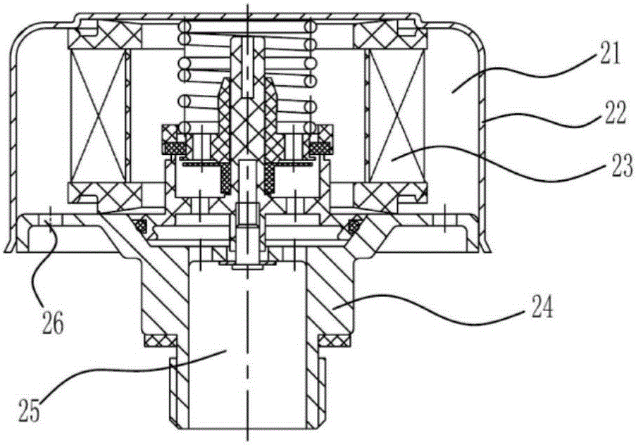
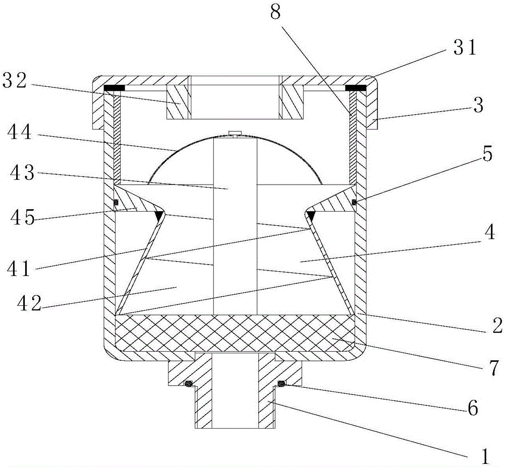
[0026] Such as Figure 1-2 As shown, the spiral separation device for hydraulic oil tank breathing apparatus includes a connecting seat 1 for connecting an oil tank, a housing 2 arranged on the connecting seat 1, and a cover 3 arranged on the housing 2, and the connecting seat 1 is provided with a vent hole , The cover 2 is provided with threaded holes for connecting the respirator, and also includes a spiral separation portion 4 provided between the housing 2 and the cover 3. The spiral separation portion 4 includes a separation cylinder 41, a spiral blade 42, a blade shaft 43 and The outer edge of the spiral blade 42 is fixed on the inner wall of the separation cylinder 41, and the inner edge is fixed on the blade shaft 43. The lower end of the blade shaft 43 is flush with the lower end of the separation cylinder 41, and the upper end extends out of the separation cylinder 41 and is connected to the separation plate. 44 is connected, and a pressure ring 8 is provided between the spiral separation part 4 and the cover 3. In an embodiment, the casing is directly much larger than the connecting seat and the vent holes are direct, so that the flow rate of the air containing oil particles in the casing is reduced, which is convenient for the oil filter to absorb oil particles; a spiral separation part is provided on the upper part of the oil filter, When the air adsorbed by the oil filter flows through the spiral channel, the remaining oil particles will adhere to the spiral blades, thereby reducing the content of oil particles in the air; the exit area of ​​the spiral separation part is reduced, and when the air flows through the exit When the air accelerates and impacts on the partition, the partition will continue to absorb some oil particles, so that the oil particles in the air are further reduced, thereby preventing the oil particles from being discharged outside the respirator to pollute the environment and affect the appearance of the hydraulic oil tank.
[0027] In this embodiment, the separation cylinder 41 is a conical cylinder, the small end of the conical cylinder is provided with a disc 45, the outer circular surface of the disc 45 is provided with a sealing groove, and the end surface is provided with a tapered hole. In the embodiment, the separation cylinder is designed as a conical cylinder to increase the outlet air flow rate, so that the outlet air impacts the baffle plate, so that a small amount of oil particles are adsorbed by the baffle plate. The tapered hole is provided for convenience The oil particles dropped from the baffle return to the cone and flow back into the shell.
[0028] In this embodiment, the lateral size of the baffle plate 44 is larger than the lateral size of the outlet at the small end of the cone, and an annular air channel is provided between the circumference of the baffle plate and the disk. In an embodiment, the lateral size of the baffle plate is larger than the lateral size of the outlet at the small end of the cone, so that all the gas ejected from the cone can impinge on the baffle plate, thereby further adsorbing oil particles.
[0029] In this embodiment, an O-ring 5 is provided on the sealing groove. In the embodiment, the O-shaped sealing ring is arranged on the outer circular surface of the disc to prevent the oily particles from leaking from the gap between the spiral separation part and the shell, thereby bringing the oily particles into the respirator and increasing the size of the respirator. The concentration of oily particles in the air causes the oil particles to be discharged outside the respirator to pollute the environment and affect the appearance of the hydraulic oil tank.
[0030] In this embodiment, one end of the connecting seat 1 is provided with a first external thread for connecting the breathing port of the fuel tank, the other end is provided with a cylindrical surface for fixing the housing 2, and an outer hexagon is provided in the middle for tightening, and the outer hexagon is close to the first outer thread. The threaded end is provided with a sealing ring groove, and a sealing ring 6 is provided on the sealing ring groove. In the embodiment, the cylindrical surface is provided on the connecting seat for the positioning of the housing and facilitates welding, and the sealing ring is provided on the outer hexagon near the first outer threaded end to prevent the air containing oil particles from leaking out of the oil tank.
[0031] In this embodiment, the cover body 3 includes a cover cylinder 31 and a connecting post 32 arranged inside the cover cylinder 31, and the threaded hole penetrates the cover cylinder 31 and the connecting post 32. In the embodiment, the threaded hole is designed to penetrate the cover cylinder and the connecting column to facilitate the connection of the respirator.
[0032] In this embodiment, the partition plate 44 is in the shape of an inverted spherical crown and is provided with oil-absorbing cotton at the lower end. In the embodiment, the baffle is designed as an inverted spherical crown shape to increase the adsorption area and after the oil-absorbing cotton absorbs a certain amount of oil particles, it is convenient for the oil particles to fall into the tapered hole.
[0033] In this embodiment, an oil filter screen 7 is further provided between the bottom of the housing 2 and the spiral separation part 4, and the oil filter screen 7 is a stainless steel mesh. In the embodiment, an oil filter screen is arranged between the bottom of the housing and the spiral separation part to absorb a large amount of oil through the oil filter screen first, so that when air is sucked in, oil particles can be brought back to the oil tank.
[0034] Finally, it should be noted that the above preferred embodiments are only used to illustrate the technical solutions of the present invention and not to limit it. Although the present invention has been described in detail through the above preferred embodiments, those skilled in the art should understand that it can be combined in form and Various changes are made to the details without departing from the scope defined by the claims of the present invention.

PUM

no PUM

Description & Claims & Application Information

We can also present the details of the Description, Claims and Application information to help users get a comprehensive understanding of the technical details of the patent, such as background art, summary of invention, brief description of drawings, description of embodiments, and other original content. On the other hand, users can also determine the specific scope of protection of the technology through the list of claims; as well as understand the changes in the life cycle of the technology with the presentation of the patent timeline. Login to view more.

Similar technology patents

Wire oxidation film grinding device

InactiveCN111482881AThe device is easy to operateavoid polluting the environment
Owner:DEQING JIAWEI CABLE

Wet sand oven-dry system

ActiveCN103090658Aavoid polluting the environmentMake full use of
Owner:SANY HEAVY IND CO LTD (CN)

PC/ABS alloy material based on waste regeneration and preparation process thereof

PendingCN113024985Aavoid polluting the environmentImprove heat resistance, tensile strength
Owner:苏州德丽雅塑胶科技有限公司

Classification and recommendation of technical efficacy words

  • avoid polluting the environment

Graphene heat-conducting anticorrosive water-based paint, and preparation and application methods thereof

ActiveCN106366710Aavoid polluting the environmentImproves corrosion protection performance
Owner:北京石墨烯技术研究院有限公司

Harmless disposal method of cyanidation tailings

ActiveCN108515073AGood cyanide removal effectavoid polluting the environment
Owner:NORTHEASTERN UNIV

Production process and equipment for preparing fertilizer from straws

PendingCN111848296AIncrease soil organic matter contentavoid polluting the environment
Owner:安吉学健再生资源股份有限公司
Why Eureka
Try Eureka