
Hydraulic tank breather

A technology for hydraulic oil tank and respirator, which is applied in the direction of oil supply tank device, fluid pressure actuating device, fluid pressure actuating system components, etc. The effect of polluting the environment

Active Publication Date: 2018-10-26
NANJING QINGZETIAN ENG MACHINERY
View PDF7 Cites 0 Cited by
  • Summary
  • Abstract
  • Description
  • Claims
  • Application Information

AI Technical Summary

Problems solved by technology

When the air in the hydraulic oil tank enters and leaves the respirator with this structure, the hydraulic oil particles contained in the air adhere to the filter cotton. When the hydraulic oil adhered to the filter cotton reaches saturation, the hydraulic oil on the filter cotton is exhaled. Under the action of airflow and gravity, it flows out through the air outlet of the respirator to pollute the environment and affect the appearance of the hydraulic oil tank

Method used


Image

  • Hydraulic tank breather
  • Hydraulic tank breather

Examples


Embodiment Construction

[0024] The preferred embodiments of the present invention will be described in detail below with reference to the accompanying drawings.

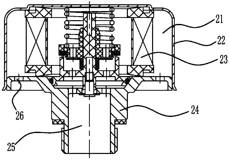
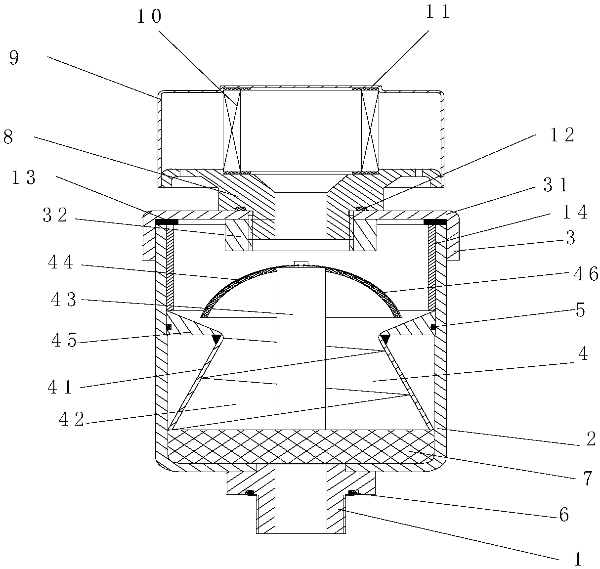
[0025] Such as Figure 1-2 As shown, the hydraulic oil tank respirator includes an upper exhalation device and a lower exhalation device arranged on the upper exhalation device, and the upper exhalation device includes an upper breathing seat 8, an upper cover 9 arranged on the upper breathing seat 8 and a set The cotton mesh filter element 10 between the upper breathing seat 8 and the upper cover 9 is provided with a first sealing gasket 11 at the contact between the cotton mesh filter element 10 and the upper breathing seat 8 and the upper cover 9, and an upper sealing gasket 11 is arranged around the top of the upper breathing seat 8. The air outlet is provided with an upper air inlet in the middle, and the lower exhalation device includes a lower breathing seat 1 for connecting the fuel tank, a housing 2 arranged on the lower breathing ...


PUM


Abstract

The invention relates to a hydraulic oil tank respirator which comprises a lower respiration base, a shell and a lower cover, wherein the lower respiration base is used for connecting an oil tank; the shell is arranged on the lower respiration base; the lower cover is arranged on the shell; an air vent is formed in the lower respiration base; a threaded hole is formed in the lower cover; the hydraulic oil tank respirator further comprises a spiral separating part arranged between the shell and the lower cover; the spiral separating part comprises a separating drum, a spiral blade, a blade shaft and a separating baffle; the outer edge of the spiral blade is fixed on the inner wall of the separating drum; the inner edge of the spiral blade is fixed on the blade shaft; the lower end of the blade shaft is aligned with the lower end of the separating drum; the upper end extends out of the separating drum and is connected with the separating baffle. The hydraulic oil tank respirator aims to reduce the concentration of oil particles arriving at an upper expiration device by an oil filter screen and the spiral separating part arranged in the lower respiration base, so that the cotton web filter element in the upper expiration device can fully absorb the oil particles and the oil particles can be prevented from flowing out of the vent hole, polluting environment and influencing the appearance of the hydraulic oil tank.

Description

technical field [0001] The invention belongs to the technical field of oil tanks and relates to a hydraulic oil tank respirator. Background technique [0002] The hydraulic oil tank is an essential oil storage container for hydraulic equipment. When the piston rod of the hydraulic cylinder is stretched out, the hydraulic pump sends the hydraulic oil to the hydraulic cylinder, and when the piston rod of the hydraulic cylinder retracts, the hydraulic oil returns. The hydraulic oil tank, so the hydraulic oil tank needs to be provided with a breathing port to communicate with the outside, so that the air in the tank can flow in and out with the hydraulic oil in and out. After the equipment works for a long time, there are many hydraulic oil particles floating in the air in the hydraulic oil tank. When the hydraulic oil returns to the hydraulic oil tank, the hydraulic oil in the hydraulic oil tank increases, and the air is discharged from the breathing port, so that Hydraulic oi...

Claims


Application Information

Patent Timeline
Patent Type & Authority Patents(China)
IPC IPC(8): F15B1/26F15B21/04
CPCF15B1/26F15B21/044
Inventor 李诗程剀
Owner NANJING QINGZETIAN ENG MACHINERY
Learn More