Rapid-clutching centrifugal type clutch

A centrifugal clutch, fast technology, applied in clutches, automatic clutches, mechanical equipment, etc., can solve the problems of inconsistent friction shoes, vibration of clutch cover, waste of electric energy, etc., to improve clutch efficiency, ensure the use effect, and ensure the action. Effect

Active Publication Date: 2017-05-31
浙江超强智控科技股份有限公司
View PDF9 Cites 4 Cited by
  • Summary
  • Abstract
  • Description
  • Claims
  • Application Information

AI Technical Summary

Problems solved by technology

[0003] In the prior art scheme, the friction shoe is in contact with the clutch cover, which requires a large enough centrifugal force to overcome the tension of the extension spring, and the change of the rotational speed is a continuous process. When the generated centrifugal force is almost equal to the tension of the extension spring, the friction The shoe is in a half-open state, which leads to the loose contact between the friction shoe and the clutch cover, which cannot drive the clutch cover to rotate. The friction shoe slips, which affects the clutch efficiency of the clutch, prolongs the contact time between the friction shoe and the clutch cover, and waste of electricity
If you choose a smaller tension spring, the friction shoe will also slip, and the clutch is too fast, and the vehicle speed is still at a low speed, then it will be connected to a high gear, which will affect the acceleration of the vehicle and cause jitter, and the small spring cannot ensure Friction shoe quick reset
Existing friction shoe clutches use multiple extension springs. After long-term use, the wear degree of each extension spring is different, which will lead to inconsistency in the action of the friction shoe of each centrifugal arm type, and affect the contact area between the friction shoe and the clutch cover. , each friction shoe cannot be in conflict with the clutch cover at the same time, which will drive the clutch cover to rotate, which will cause the clutch cover to vibrate and affect the use effect of the clutch

Method used


Image

  • Rapid-clutching centrifugal type clutch
  • Rapid-clutching centrifugal type clutch
  • Rapid-clutching centrifugal type clutch

Examples


Embodiment Construction

[0041] In order to make the object, technical solution and advantages of the present invention clearer, the present invention will be further described in detail below in conjunction with the accompanying drawings and embodiments. It should be understood that the specific embodiments described here are only used to explain the present invention, not to limit the present invention.

[0042] On the contrary, the invention covers any alternatives, modifications, equivalent methods and schemes within the spirit and scope of the invention as defined by the claims. Further, in order to make the public have a better understanding of the present invention, some specific details are described in detail in the detailed description of the present invention below. The present invention can be fully understood by those skilled in the art without the description of these detailed parts.

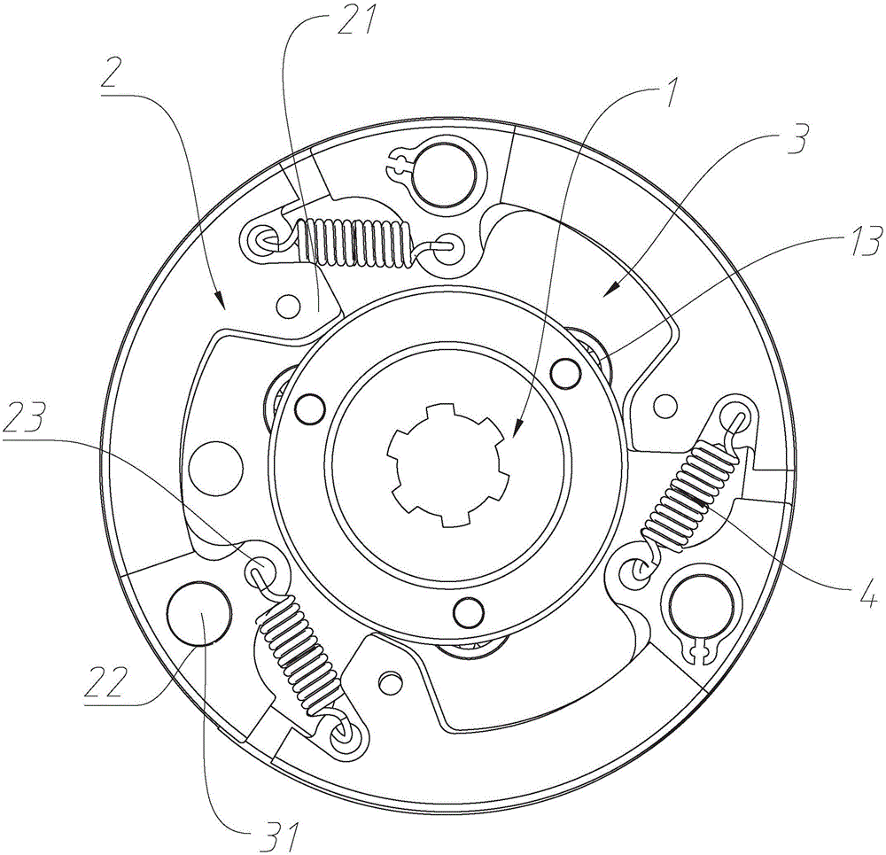
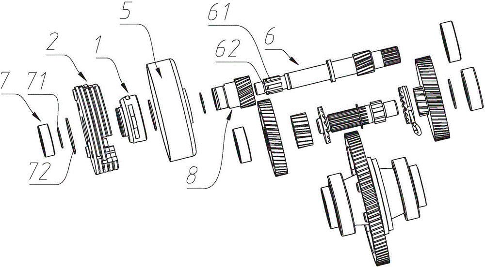
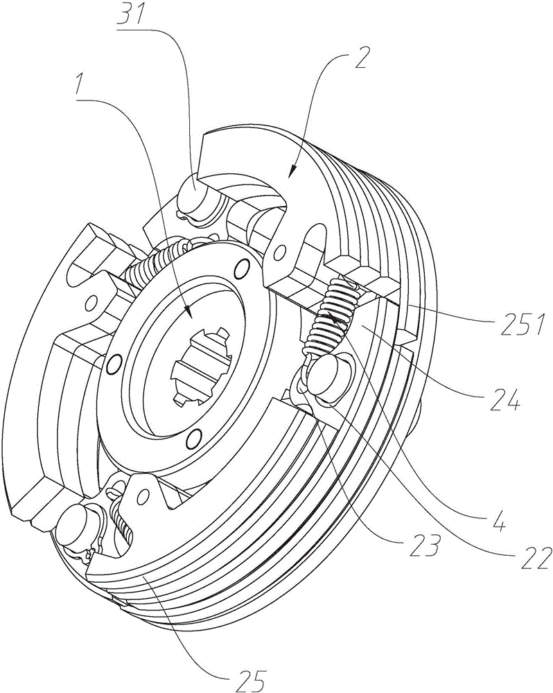
[0043] Such as Figure 1-2 The specific embodiment shown is a centrifugal clutch with fast clutching,...


PUM


Abstract

The invention discloses a rapid-clutching centrifugal type clutch and belongs to the technical field of clutch equipment. According to the scheme in the prior art, friction shoe blocks need large enough centrifugal force to overcome the tension of tension springs when making contact with clutch covers, so that the clutching efficiency of a clutch is affected; and the actions of all the centrifugal arm type friction shoe blocks are not consistent, so that the contacting areas of the friction shoe blocks and the clutch covers are affected. A shoe pushing piece is arranged on the clutch, pushing edges are arranged on the shoe pushing piece and used for pushing the extending parts of friction shoe blocks to enable the friction shoe blocks to spread radially, and accordingly the friction shoe blocks spread rapidly to abut against clutch covers to drive the clutch covers to rotate. The tension of tension springs can be overcome accurately according to preset centrifugal force, sliding of the friction shoe blocks is avoided effectively, the clutching efficiency of the clutch is improved, and power energy is saved; and additionally it is guaranteed that the friction shoe blocks are consistent in action, so that the using effect of the clutch is guaranteed.

Description

technical field [0001] The invention relates to a fast clutch centrifugal clutch, which belongs to the technical field of clutch equipment. Background technique [0002] Centrifugal clutches generally have a shoe-type structure, which is installed on the rotating shaft of the motor. The centrifugal clutch realizes the high-low gear shifting of the motor or engine through the combination and separation of the friction shoes and the clutch cover. Existing centrifugal clutches generally consist of three centrifugal arm-type friction shoes. Each centrifugal arm-type friction shoe is spot-welded from several steel plates with different shapes. Each centrifugal arm-type friction shoe The fixed point end of the friction shoe is hinged with the chassis through a pin shaft, the moving point end is connected with the fixed point end of another friction shoe through a tension spring, and the chassis is splined with the rotating shaft. When the rotating shaft drives the chassis to r...

Claims


Application Information

Patent Timeline
Patent Type & Authority Applications(China)
IPC IPC(8): F16D43/18
CPCF16D43/18F16D2043/145
Inventor 林玲龙周雪峰
Owner 浙江超强智控科技股份有限公司
Why Eureka
Try Eureka