
Electromagnetically ventilating spring pressure brake in the form of a multi-circle triangular brake

A technology of spring pressure and brakes, applied in the direction of brake types, brake components, automatic brakes, etc., can solve the problems of local manufacturing of complex parts, operation and installation of brakes, etc., to achieve low manufacturing costs, simple and compact structure, and resource protection Effect

Active Publication Date: 2017-05-31
CHRISTIAN MAYR GMBH & CO KG
View PDF10 Cites 3 Cited by
  • Summary
  • Abstract
  • Description
  • Claims
  • Application Information

AI Technical Summary

Problems solved by technology

[0015] The disadvantage of this so-called four-stage brake is its huge number of locally manufactured and complex components, which brings about an increase in the operating and installation costs of the brake

Method used


Image

  • Electromagnetically ventilating spring pressure brake in the form of a multi-circle triangular brake
  • Electromagnetically ventilating spring pressure brake in the form of a multi-circle triangular brake
  • Electromagnetically ventilating spring pressure brake in the form of a multi-circle triangular brake

Examples


Embodiment Construction

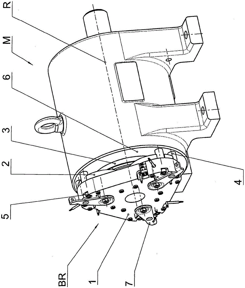
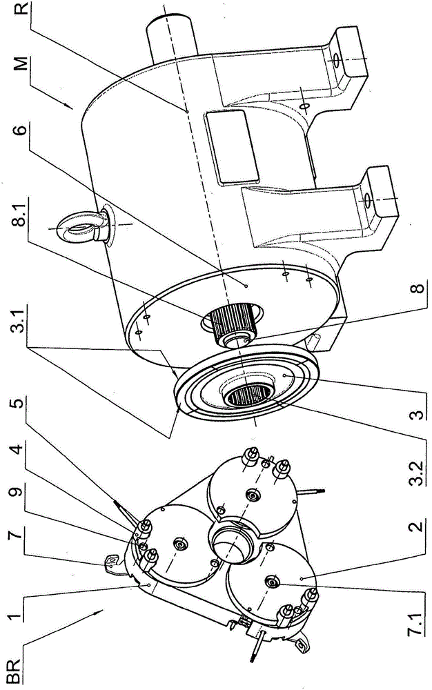
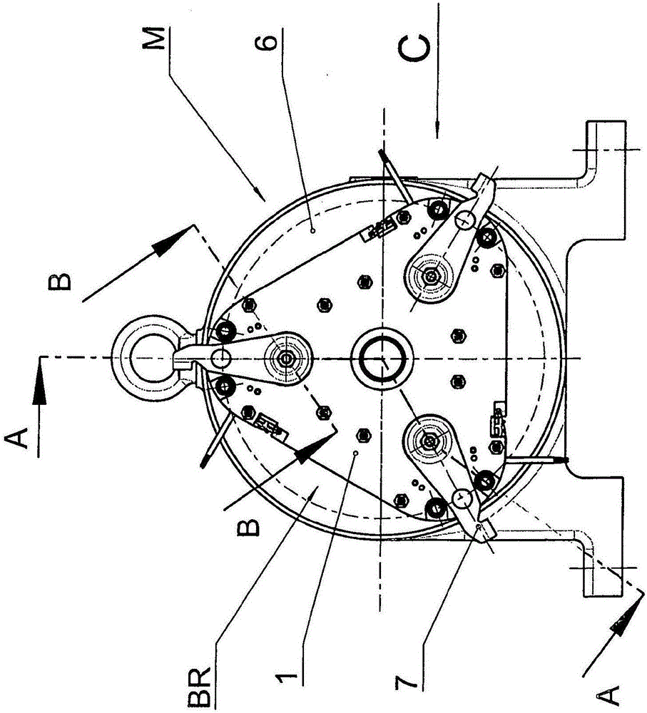
[0041] From figure 1 The basic structure of the spring pressure brake BR according to the invention and its mounting on the end wall 6 of the motor M can be seen in . Accordingly, the spring pressure brake BR is mounted concentrically to the axis of rotation R of the motor M on the machine wall 6 , wherein the coil carrier 1 of the brake BR is fixedly connected to the motor M via spacer bushes 4 and bolts 5 .

[0042] The coil former 1 is equipped with three armature disks 2 which are axially movable relative to the coil former 1 but mounted in a rotationally fixed manner. Between the armature disk 2 and the mating friction surface 6 there is a brake rotor 3 which is equipped with an annular friction lining 3 . On the side of the coil carrier facing away from the motor M there are three manual release levers 7 which are operatively connected to the armature disk 2 of the spring pressure brake BR.

[0043] Further details of the spring pressure brake BR according to the inven...


PUM


Abstract

The invention relates to an electromagnetically ventilating spring pressure brake (BR). The pressure brake is installed on a machine wall plate or a similar structure and comprises an axially movable brake rotor (3). The brake rotor comprises friction linings (3.1) which are continuous on two sides, i.e., the left side and the right side. The pressure brake (BR) comprises a coil rack (1) and multiple armature discs (2) disposed to the coil rack (1). In order to achieve the braking function, the brake rotor (3) is allowed to press the machine wall plate (6) or the similar structure on one side (left side) and press the armature discs (2) on the other side (right side). The pressure brake (BP) comprises the coil rack (1) with a triangular basic cross section. Three armature discs (2) are disposed to the coil rack (1).

Description

technical field [0001] The present application relates to an electromagnetically released spring pressure brake. Background technique [0002] In the field of lift technology, crane technology and shaft vehicles with vertical / vertical movements, electromagnetically released spring-loaded brakes have been developed for braking and holding the corresponding drives to a standstill. [0003] Brake systems of this type must be designed redundantly for safety reasons, which can be achieved by mounting several separate brakes each with only one brake circuit on the drive or by installing only one brake with several internal brake circuits brake to achieve. [0004] For this, it is customary that each brake circuit present makes an equal contribution to the total braking torque of the brake. In this context, it is sufficient with regard to the requirement for redundancy that, in the event of a fault / failure in a brake circuit, 100% of the torque required for braking and stopping t...

Claims


Application Information

Patent Timeline
IPC IPC(8): F16D59/02
CPCF16D59/02F16D65/186F16D2121/22
Inventor G·克林勒L·布劳恩C·德罗普曼J·艾森布格尔M·菲希特尔
Owner CHRISTIAN MAYR GMBH & CO KG
Learn More