Boiler deslagging cooling system and boiler deslagging cooling method

A slag cooling and boiler technology, applied in lighting and heating equipment and other directions, can solve the problems of worsening the operating environment, damage to the drum slag cooler, gas leakage, etc., to achieve the effect of simple process, avoidance of safety accidents, and prevention of gas leakage.

Pending Publication Date: 2017-05-31
SHENWU TECH GRP CO LTD
View PDF0 Cites 1 Cited by
  • Summary
  • Abstract
  • Description
  • Claims
  • Application Information

AI Technical Summary

Problems solved by technology

[0002] As a boiler slag removal device, the drum slag cooler is widely used in power plant circulating fluidized bed boilers and solid fuel (coal, biomass, domestic waste, medium oil, etc.) gasification and pyrolysis furnaces in the energy and chemical industries. The sealing of the slag machine is poor, and the hot slag will carry a small amount of gas when it is discharged from the slag discharge pipe of the boiler to the slag cooler of the drum, and these gases are easily leaked from the rotary connection between the feeding device or the discharging device and the drum
[0003] When the flammable, explosive and toxic gas produced in the energy and chemical industry leaks, if it is in the continuous slag discharge period, the mixture of high-temperature gas and a small amount of fine powder ash will be discharged into the drum cooling slag machine along with the hot slag. The internal press

Method used


Image

  • Boiler deslagging cooling system and boiler deslagging cooling method
  • Boiler deslagging cooling system and boiler deslagging cooling method
  • Boiler deslagging cooling system and boiler deslagging cooling method

Examples


Embodiment 1

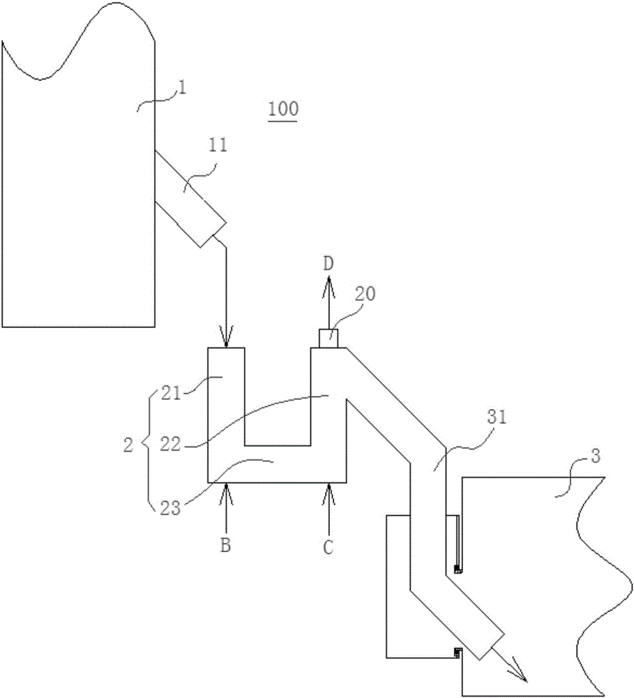
[0063] In the first embodiment, the slagging device 2 is a U-shaped slagging device 2, nitrogen is used as the loosening gas B and fluidizing gas C, and the semi-coke discharged from the boiler 1 as a pyrolysis furnace is cooled as an example to explain in detail.

[0064] refer to figure 1 , the semi-coke (minimum average fluidization velocity Umf=0.2m / s) discharged from the slag discharge pipe 11 of the boiler 1 as a pyrolysis furnace with a particle size of 0-8mm (but not 0mm) enters under the action of gravity The first tube 21 of the U-shaped slagging device 2 forms a material seal. Under the action of the material seal, the pyrolysis gas discharged from the boiler 1 as the pyrolysis furnace cannot enter the second tube under the action of the material seal in the first tube 21. Two pipes 22, at the same time, blast into the U-shaped slagging device 2 an inert gas-nitrogen that does not react with semi-coke and pyrolysis gas as loosening gas B and fluidization gas C, and ...

Embodiment 2

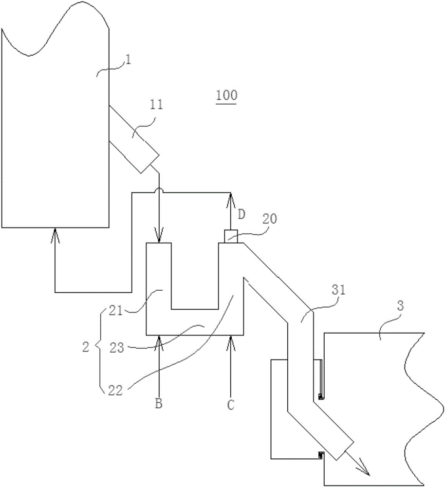
[0066] refer to figure 2 , the structure of the second embodiment is substantially the same as that of the first embodiment, the difference is that in this embodiment, the tail gas port 20 is directly connected to the boiler 1 instead of being connected to the atmosphere. That is to say, the nitrogen gas discharged through the tail gas port 20 can enter the boiler 1 and be used as a pyrolysis protection gas, thereby reducing costs and improving utilization efficiency.

Embodiment 3

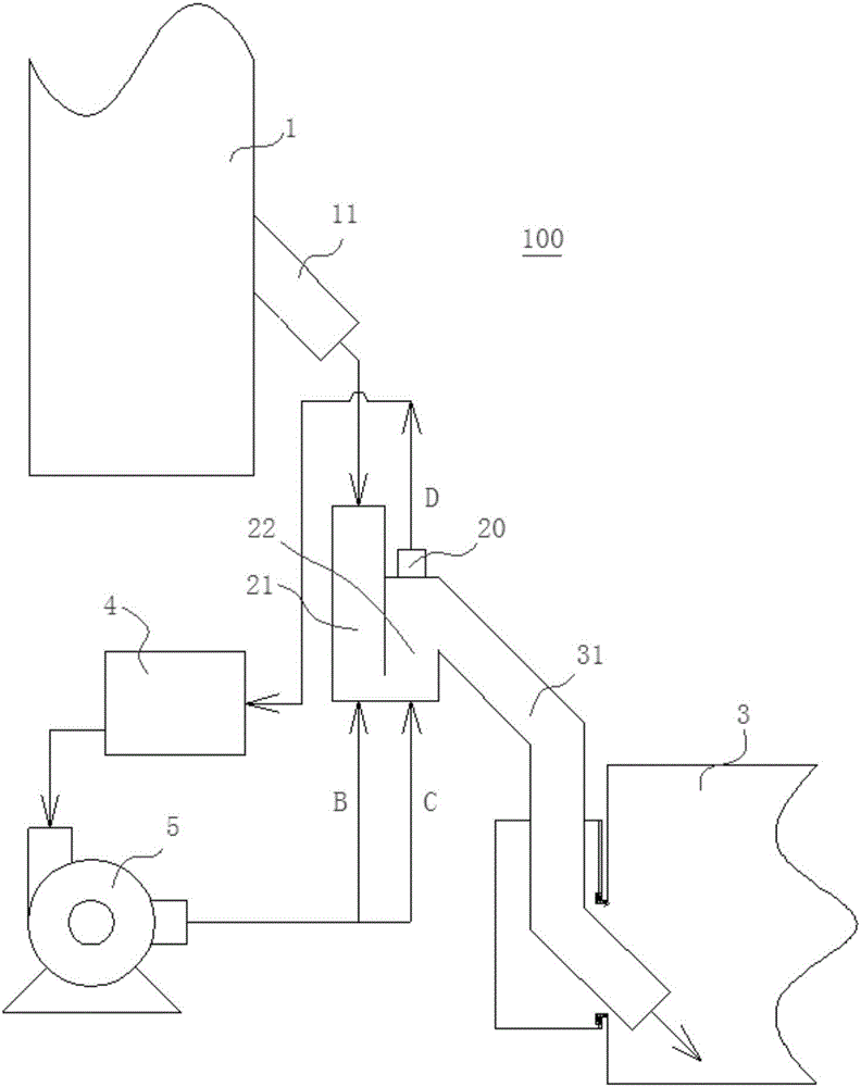
[0068] In the third embodiment, the slagging device 2 is a J-type slagging device 2, nitrogen is used as the loosening gas B and the fluidizing gas C, and the semi-coke discharged from the boiler 1 as a gasifier is cooled as an example to illustrate in detail.

[0069] refer to image 3 , the semi-coke (minimum average fluidization velocity Umf=0.05m / s) discharged from the slagging pipe 11 of the boiler 1 as the gasification furnace with a particle size of 0-1 mm enters the J-shaped slagging device 2 under the action of gravity In the first pipe 21, a material seal is formed. Under the action of the material seal, the synthetic gas discharged from the boiler 1 as a gasification furnace cannot enter the J-shaped second pipe 22 under the effect of the material seal in the first pipe 21. J-type slagging device 2 blows inert gas-nitrogen that does not react with semi-coke and synthetic gas as loosening gas B and fluidization gas C, the flow rate of loosening gas B is 0.025-0.075m / ...


PUM


Abstract

The invention discloses a boiler deslagging cooling system and a boiler deslagging cooling method. The boiler deslagging cooling system comprises a boiler, a cooling roller and a slag discharging device, wherein the slag discharging device comprises a first pipe, a second pipe, a first air feeding device and a second air feeding device, the inlet end of the first pipe is commucniated with a slag outlet of the boiler, and the outlet end of the first pipe is lower than the inlet end of the first pipe; the inlet end of the second pipe is communicated with the outlet end of the first pipe, the outlet end of the second pipe is communicated with a slag inlet of the cooling roller, the outlet end of the second pipe is higher than the inlet end of the second pipe or aligns at the inlet end of the second pipe, and a tail gas opening is formed in the top of the second pipe; and the first air feeding device is used for feeding loose air into the outlet end of the first pipe, and the second air feeding device is used for feeding fluidifyed air into the inlet end of the second pipe. By means of the boiler deslagging cooling system, the problem of air leakage can be effectively prevented, and safety accidents can be avoided.

Description

technical field [0001] The invention relates to the technical field of boiler slag cooling machines, in particular to a boiler slag discharge cooling system and a boiler slag discharge cooling method. Background technique [0002] As a boiler slag removal device, the drum slag cooler is widely used in power plant circulating fluidized bed boilers and solid fuel (coal, biomass, domestic waste, medium oil, etc.) gasification and pyrolysis furnaces in the energy and chemical industries. The sealing of the slag machine is poor, and the hot slag will carry a small amount of gas when it is discharged from the slag discharge pipe of the boiler to the slag cooler of the drum, and these gases are easily leaked from the rotary connection between the feeding device or the discharging device and the drum . [0003] When the flammable, explosive and toxic gas produced in the energy and chemical industry leaks, if it is in the continuous slag discharge period, the mixture of high-tempera...

Claims


Application Information

Patent Timeline
IPC IPC(8): F23J1/06
CPCF23J1/06
Inventor 刘周恩史雪君苏二强吴黎阳余海鹏黄伟孙宝林史东军吴道洪
Owner SHENWU TECH GRP CO LTD
Why Eureka
Try Eureka