Object placement rack and refrigerator provided with rack

A storage rack and storage technology, which is applied to home appliances, household refrigeration devices, lighting and heating equipment, etc. It can solve the problems that users cannot see the refrigerator items clearly, the overall size of the backlight panel is large, and the brightness of the light is weakened, so as to prevent Direct light to the human eye, improve light utilization, and achieve decorative and lighting effects

Inactive Publication Date: 2017-05-31
HAIER SMART HOME CO LTD +1
View PDF8 Cites 5 Cited by
  • Summary
  • Abstract
  • Description
  • Claims
  • Application Information

AI Technical Summary

Problems solved by technology

[0002] Existing refrigerators mostly use backlight panels for lighting in the box, but the backlight panels are not only large in overall size, complex in structure, and high in cost, but also the laser heat conduction plates used in existing backlight panels cannot achieve micro-nano fine structures. low efficiency for the size of the backlight
[0003] Moreover, in the prior art, in order to achieve uniform lighting, it is usually necessary to install a diffuser plate to astigmatize the light, but the setting of the diffuser plate will weaken the brightness of the light
Not only that, but the items on the shelf can also block the light, so that the user cannot see the items in the refrigerator when the indoor ambient light is insufficient

Method used


Image

  • Object placement rack and refrigerator provided with rack
  • Object placement rack and refrigerator provided with rack
  • Object placement rack and refrigerator provided with rack

Examples


Embodiment Construction

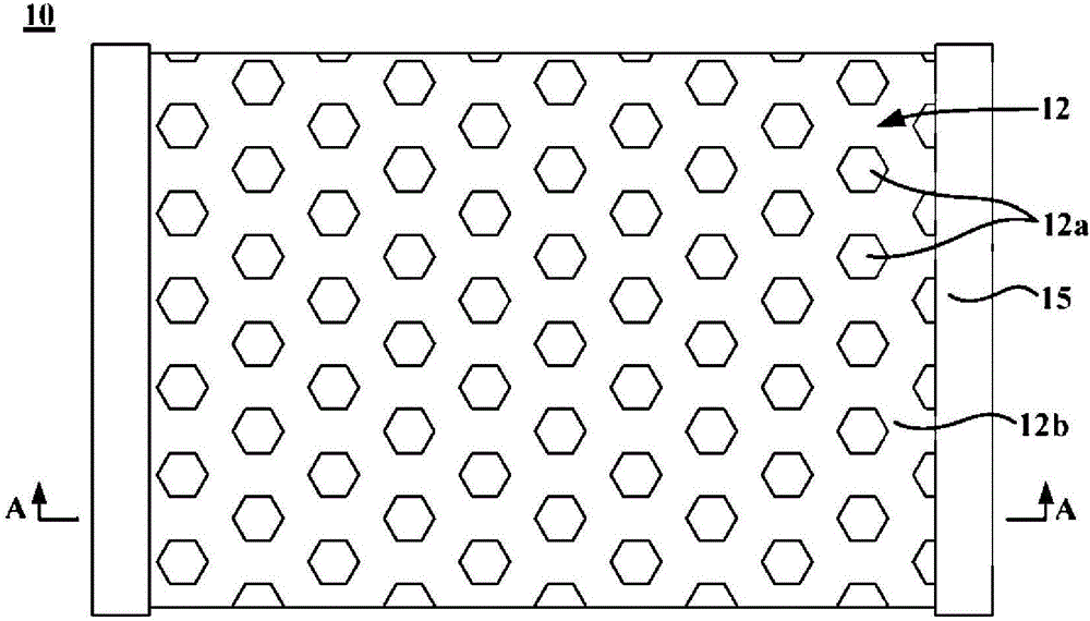
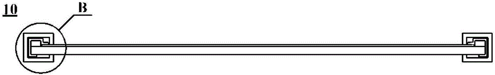
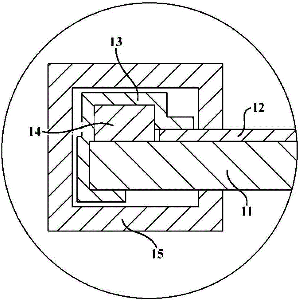
[0028] figure 1 is a schematic top view of a shelf 10 according to an embodiment of the present invention; figure 2 is along figure 1 A schematic sectional view taken along the cutting line A-A in ; image 3 yes figure 2 Schematic partial enlargement of region B in middle. see figure 1 , 2 and 3, the shelf 10 may generally include a shelf base 11 for supporting items, and the shelf base 11 may be made of a plate such as PMMA or PC. For example, it can be made of PMMA plate with a thickness of 2-3mm. The shelf 10 also includes a light emitting member 14 and a reflective foil 13 .

[0029] Specifically, the light emitting member 14 is disposed on the shelf base 11 and arranged linearly on at least one lateral edge of the shelf base 11 for providing light to the shelf 10 . In some preferred embodiments, the light emitting member 14 can adopt cold light sources such as LED lamp beads. In some embodiments, the light emitting members 14 may be linearly arranged on the rea...


PUM


Abstract

The invention provides an object placement rack. The object placement rack comprises an object placement substrate used for supporting objects and is characterized in that the object placement rack further comprises illuminating members and reflective foils; the illuminating members are arranged on the object placement substrate and arrayed at least one lateral edge of the object placement rack in a linear manner and used for providing light for the object placement rack; and the reflective foils are arranged to wrap the surfaces of the illuminating members and used for preventing light emitted by the illuminating members from overflowing the object placement rack. The object placement rack and the refrigerator provided with the rack have following beneficial effects: by linearly arraying the illuminating members on the edge of the object placement substrate and wrapping the reflective foils on the surfaces of the illuminating members, the object placement rack has a simple and compact structure; no extra storage space is occupied; the arrangement of the reflective foils helps prevent light emitted by the illuminating members from overflowing the object placement rack and prevent light from directly shining into human eyes, thereby increasing light utilization rate of the illuminating members; and in addition, the reflective foils help dissipate heat of the illuminating members so that service lifetime of lamp beads is prolonged.

Description

technical field [0001] The invention relates to a lighting device, in particular to a shelf and a refrigerator with the shelf. Background technique [0002] Existing refrigerators mostly use backlight panels for lighting in the box, but the backlight panels are not only large in overall size, complex in structure, and high in cost, but also the laser heat conduction plates used in existing backlight panels cannot achieve micro-nano fine structures. The size of the backlight is inefficient. [0003] Moreover, in the prior art, in order to achieve uniform lighting, it is usually necessary to install a diffuser plate to astigmatize the light, but the arrangement of the diffuser plate will weaken the brightness of the light. Not only that, but the items on the shelf can also block the light, so that when the indoor ambient light is insufficient, the user cannot see the items in the refrigerator clearly. Considering comprehensively, a lighting device with simple structure, low ...

Claims


Application Information

Patent Timeline
Patent Type & Authority Applications(China)
IPC IPC(8): F25D25/02F25D27/00
CPCF25D25/02F25D27/00
Inventor 李洪涛费斌刘振宇赵斌堂李登强刘鹏贺立军
Owner HAIER SMART HOME CO LTD
Why Eureka
Try Eureka