
Spatial resolution test board and spatial resolution test method for electroluminescent defect detector

A spatial resolution and luminescence technology, which is applied in optical instrument testing, machine/structural component testing, optical performance testing, etc., can solve problems such as inapplicable electroluminescent defect detectors, and achieve easy results and convenient operation Effect

Active Publication Date: 2017-05-31
FUJIAN METROLOGY INST
View PDF11 Cites 6 Cited by
  • Summary
  • Abstract
  • Description
  • Claims
  • Application Information

AI Technical Summary

Problems solved by technology

For the electroluminescence defect detector, its operating spectrum band is near infrared, and the resolution test board itself cannot emit near-infrared light, so this method is not suitable for direct evaluation of the electroluminescence defect detector

Method used


Image

  • Spatial resolution test board and spatial resolution test method for electroluminescent defect detector
  • Spatial resolution test board and spatial resolution test method for electroluminescent defect detector
  • Spatial resolution test board and spatial resolution test method for electroluminescent defect detector

Examples


Embodiment 1

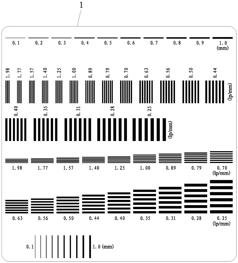
[0039] Such as figure 1As shown, four detection block groups are distributed on the spatial resolution test board 1, and each of the detection block groups includes a plurality of detection squares with different stripe line widths, and each of the detection squares is composed of a plurality of identical lines. Wide black and white spaced line pair stripes, the direction of the line pair stripes in different detection block groups is different, the direction of the line pair stripes in the same detection block group is the same, and the directions of the line pair stripes in the detection block group are horizontal direction, Vertical direction, left oblique direction of 45° and right oblique direction of 45°; the width of a single stripe in the line pair stripes ranges from 0.25mm to 1.0mm, and the plurality of detected squares in each detection block group The line width of the stripes between the detection squares is arranged gradually; the spatial resolution test board 1 ...

Embodiment 2

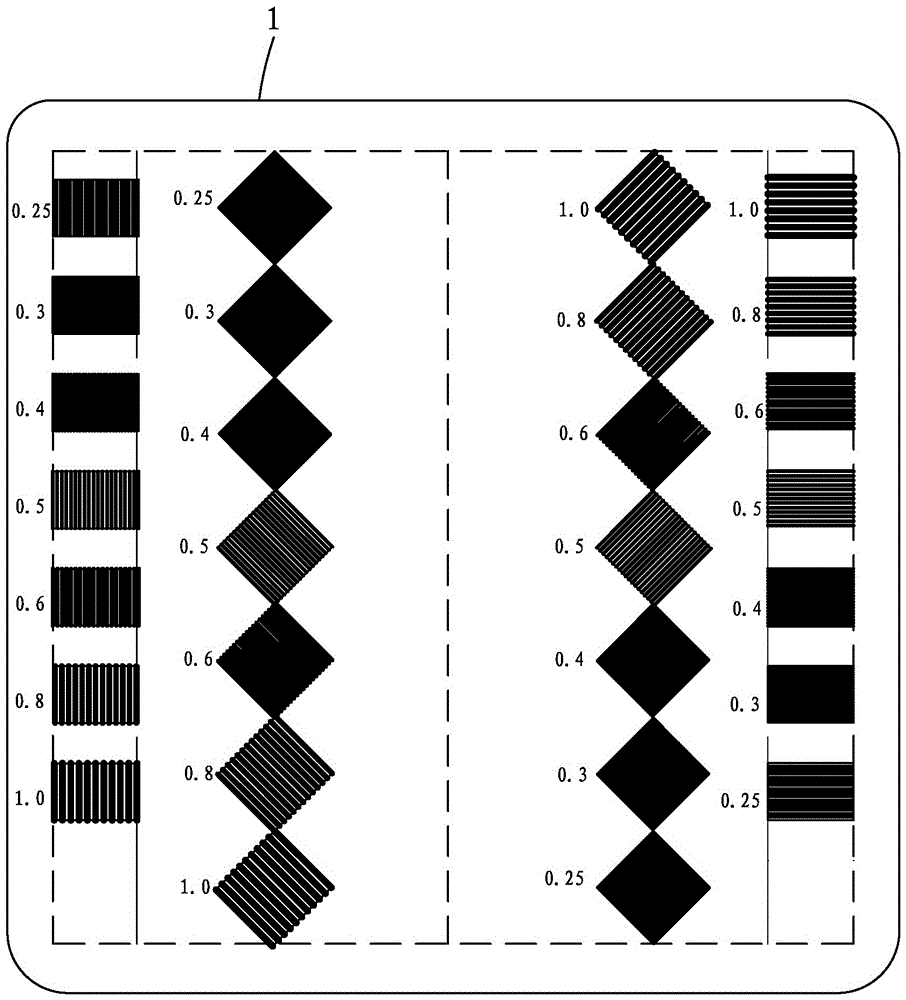
[0041] Such as figure 2 As shown, two detection square groups are distributed on the said spatial resolution test board 1, each said detection square group comprises a plurality of detection squares with different stripe line widths, and each said detection square consists of a plurality of identical lines Wide black and white spaced line pair stripes, the direction of the line pair stripes in different detection block groups is different, the direction of the line pair stripes in the same detection block group is the same, and the directions of the line pair stripes in the detection block group are horizontal direction and horizontal direction respectively. Vertical direction: the width of a single stripe in the line pair stripes ranges from 0.1mm to 2.0mm, and the width of a single stripe in a plurality of detection squares in each detection square group is in a proportional sequence or an equal difference Regular distribution of sequences; the spatial resolution test board...


PUM


Abstract

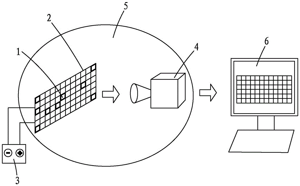
The invention provides a spatial resolution test board for an electroluminescent defect detector. The spatial resolution test board capable of transmitting near-infrared light is characterized in that a plurality of detection square block groups are distributed on the spatial resolution test board, every detection square block group comprises a plurality of detection square blocks with different line-pair stripe widths, every detection square block comprises a plurality of black-white alternated line-pair stripes, the line-pair stripes in different detection square block groups are different in direction, the line-pair stripes in every detection square block group are the same in direction, and black-white stripe bodies in every line-pair stripe are the same in width. The invention further provides a spatial resolution test method for the electroluminescent defect detector. The spatial resolution test board and the spatial resolution test method are capable of detecting spatial resolution of the electroluminescent defect detector.

Description

technical field [0001] The invention relates to the technical field of electroluminescent defect detector testing, in particular to a spatial resolution test board and a test method of an electroluminescent defect detector. Background technique [0002] The electroluminescence detector (EL detector) checks whether there are hidden cracks in the photovoltaic cell module through the electroluminescence of the photovoltaic cell module. The main way to realize it is to use the near-infrared camera for imaging detection. The most important indicator of detector performance, spatial resolution is usually also called spatial resolution, which means the ability to resolve spatial features, but there is no suitable test method yet, and there is no imaging performance for photovoltaic cell module EL defect detectors. Specification for conducting calibration tests. In the field of conventional visible light camera imaging resolution, the international standard ISO12233 mentions the us...

Claims


Application Information

Patent Timeline
Patent Type & Authority Applications(China)
IPC IPC(8): G01M11/02H02S50/15
CPCH02S50/15G01M11/00Y02E10/50
Inventor 林剑春杨爱军李杰沈熠辉沈怿珩
Owner FUJIAN METROLOGY INST
Learn More