Lighting control circuit for vehicle lighting equipment

a technology for controlling circuits and lighting equipment, which is applied in the direction of identification means, instruments, transportation and packaging, etc., can solve the problems of increasing circuit development costs, increasing product cost, and so as to reduce the cost of wirings and eliminate noise components. , the effect of reducing the number of wirings

Inactive Publication Date: 2006-03-16
KOITO MFG CO LTD
View PDF8 Cites 29 Cited by
  • Summary
  • Abstract
  • Description
  • Claims
  • Application Information

AI Technical Summary

Benefits of technology

[0010] (Effect) Since the current supplying means take the same action on the same control signal respectively, such current supplying means can cause respective semiconductor light sources to take the same action even when types of the semiconductor light sources connected to respective current supplying means are different. For example, assume that an analog signal is used as the control signals, ON / OFF and dimming of the semiconductor light source are controlled by the voltage of the analog signal, and the light source is lighted by 5 V, 0 V, and 2.5 V in a full lighting mode, a non-lighting mode, and a 50% dimmed lighting mode respectively. The semiconductor light sources connected to the current supplying means are turned on in a full lighting mode when 5 V is input into the current supplying means as the control signal, and the semiconductor light sources connected to the current supplying means are turned off when 0 V is input into the current supplying means as the control signal. Also, the semiconductor light sources connected to the current supplying means are turned on in a 50% dimmed lighting mode when 2.5 V is input into the current supplying means as the control signal. In this manner, since all the current supplying means take the same action against the control signal, there is no need to take the hardware treatment of every vehicle or every product, and in addition this lighting control circuit for the vehicle lighting equipment can be assembled not to correlate the control signal with each current supplying means on a one-to-one basis.
[0011] In accordance with one or more embodiments, the control signal generating means includes a pair of power supply input terminals connected to a DC power supply loaded on the vehicle, and a plurality of power supply output terminals for distributing a DC power supplied to the pair of power supply input terminals to the current supplying means, and also includes a reverse-connected protecting element connected to one power supply input terminal of the pair of power supply input terminals or a surge protecting element for absorbing a surge voltage applied between the pair of power supply input terminals, or a noise filter for eliminating a noise component superposed onto a DC signal being input via the reverse-connected protecting element and then outputting the DC signal, from which the noise component is eliminated, to the power supply output terminals;
[0012] (Effect) When the DC power that is input into a pair of power supply input terminals from the DC power supply loaded on the vehicle is supplied to a plurality of power supply output terminals via the reverse-connected protecting element or the surge protecting element or the noise filter, such DC power is distributed to respective supply units from the power supply output terminals. Therefore, the number of wirings can be reduced with respect to the case where the configuration for supplying the DC power to respective supply units from the DC power supply loaded on the vehicle is employed, and also a reduction in costs required for the wirings can be achieved. Also, in a case of a DC voltage with different polarities applied to a pair of power supply input terminals, applying the reverse voltage to the current supplying means can be prevented by the reverse-connected protecting element. In addition, in case the surge voltage is applied between a pair of power supply input terminals, such surge voltage can be absorbed by the surge protecting element. Further, in case the signal containing the noise is input from a pair of power supply input terminals, this noise component can be eliminated by the noise filter.

Problems solved by technology

If individual circuit developments are carried out to get various variations, the manufacturer is forced to put a huge amount of development costs in such developments.
Consequently, an increase in cost of the product is caused with an increase in the circuit development costs.

Method used


Image

  • Lighting control circuit for vehicle lighting equipment
  • Lighting control circuit for vehicle lighting equipment
  • Lighting control circuit for vehicle lighting equipment

Examples


second embodiment

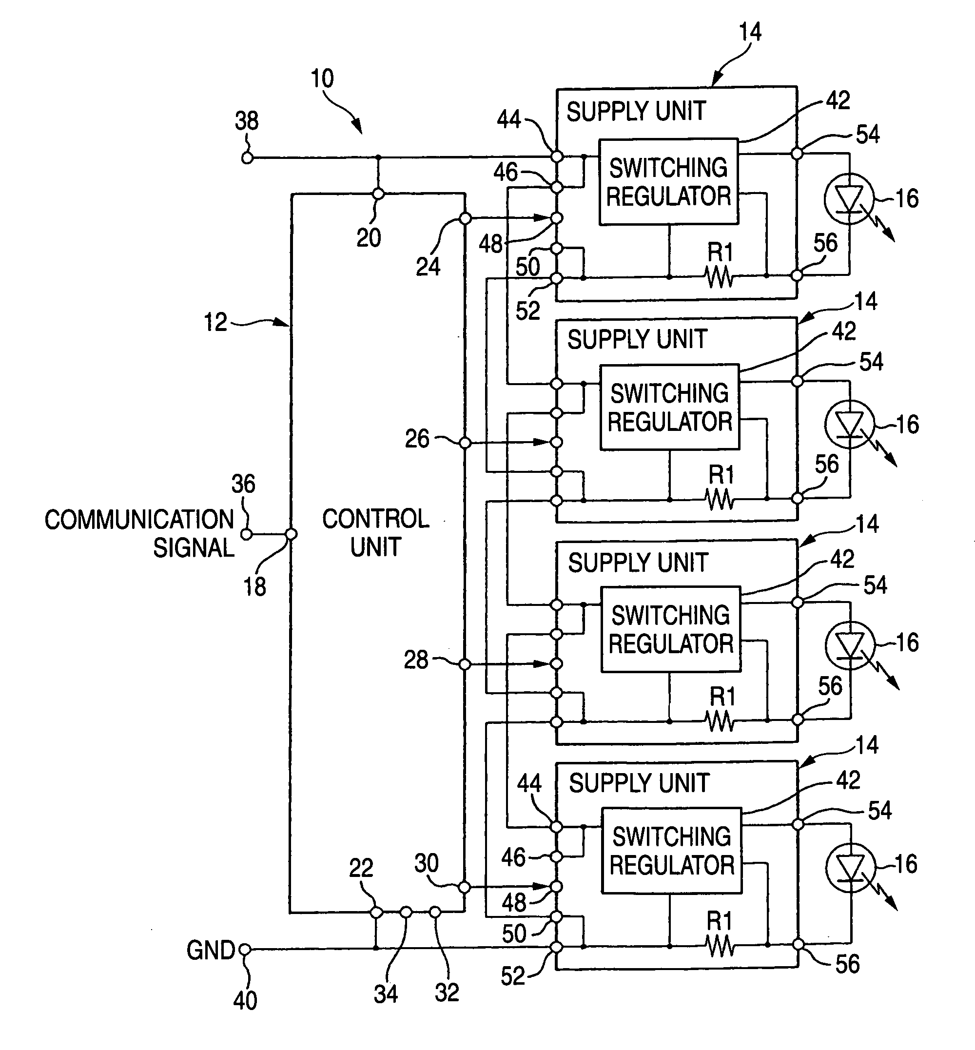
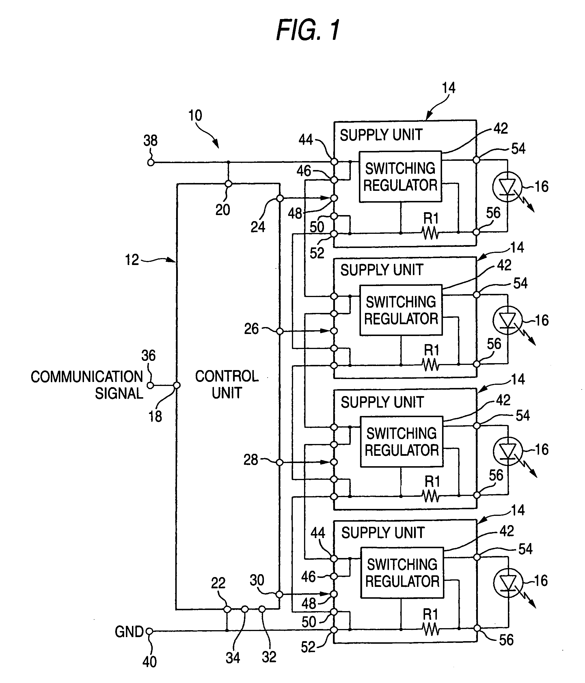
[0045] Next, the present invention will be explained with reference to FIG. 4 and FIG. 5. In the present embodiment, a power supply portion 12a is provided to the control unit 12, then the DC power is introduced into the power supply portion 12a from the battery, and then the DC power (DC signal) is distributed to respective supply units 14 from the power supply portion 12a. Remaining configurations are similar to those in FIG. 1.

[0046] More specifically, the power supply portion 12a has a diode D2 as a reverse-connected protecting element, a Zener diode Z1 as a surge protecting element, and a noise filter consisting of capacitors C5, C6 and a coil L1, and a plurality of power supply output terminals 70, 72, 74, 76, 78, 80, 82, 84 are provided to the output side of the noise filter. The anode side of the diode D2 is connected to the power supply input terminal (+B) 38 via the terminal 20, while the cathode side thereof is connected to the power supply input terminal (GND) 40 via the...

third embodiment

[0050] Next, the present invention will be explained with reference to FIG. 6. In the present embodiment, an abnormality sensing means for outputting an abnormal signal on a control signal line CL, which connects the distribution terminal 24 (26, 28, 30) of the control unit 12 and the terminal 48 of the supply unit 14, when the control unit 12 senses an abnormality of the LED 16 is provided to each supply unit 14. Also, an abnormal information outputting means for outputting an abnormal information when the abnormal information is input into the control unit 12 from any one of the supply units 14 via the control signal line CL is provided to the control unit 12.

[0051] More specifically, as the abnormality sensing means, resistors R7, R8, R9, R10, an NPN transistor 86, and comparators 88, 90 are provided to each supply unit 14. When a current If of the LED 16 is reduced lower than a set value, the comparator 88 decides the abnormality of the LED 16, e.g., a short-circuit abnormality ...


PUM


Abstract

A control unit for generating control signals in response to a communication signal fed from a vehicle, and a plurality of supply units for controlling a supply F of current to respective LEDs in compliance with the control signals generated by the control unit are provided. The control unit changes contents of the control signals in answer to the contents of the communication signal, i.e., to meet to changes of specifications when contents of the communication signal are different every type of a car or every vehicle, whereby standardization of circuit configurations can be achieved.

Description

BACKGROUND OF THE INVENTION [0001] 1. Technical Field [0002] The present invention relates to a lighting control circuit for vehicle lighting equipment and, more particularly, a lighting control circuit for vehicle lighting equipment constructed to control the lighting of a semiconductor light source that is composed of a semiconductor light emitting device. [0003] 2. Related Art [0004] In the prior art, the vehicle lighting equipment using the semiconductor light emitting device such as LED (Light Emitting Diode), or the like as the light source is known (for example, JP-A-2002-231013 (page 2 to page B4, FIG. 1 to FIG. 5)). In case the vehicle lighting equipment is constructed by using the LED as the light source, a wide variety of specifications are provided for such lighting equipment because the lighting equipment acts the eye of the vehicle and also the design aspect is looked upon as important. For example, according to the vehicle (type of a car), the number of used LEDs is d...

Claims


Application Information

Patent Timeline
Patent Type & Authority Applications(United States)
IPC IPC(8): B60L1/14B60Q1/26
CPCH05B33/0842H05B33/0815H05B45/385H05B45/50H05B45/10H05B45/3725
Inventor ITO, MASAYASUTAKEDA, HITOSHI
Owner KOITO MFG CO LTD
Why Eureka
Try Eureka