A method for finely detecting the working state of the suction nozzle

A working state, fine detection technology, applied in the direction of measuring devices, mechanical parts testing, measuring flow/mass flow, etc., can solve problems such as waste, nozzle comparison results cannot be known by the host computer, and cannot be set arbitrarily.

Active Publication Date: 2020-04-07
GKG PRECISION MACHINE
View PDF12 Cites 0 Cited by
  • Summary
  • Abstract
  • Description
  • Claims
  • Application Information

AI Technical Summary

Problems solved by technology

[0003] At present, the state detection of the suction nozzle in the market mainly uses the analog voltage value fed back by the flow sensor in the suction nozzle, and compares the analog voltage fed back by the sensor with the comparison voltage composed of a potentiometer and a resistor, and then judges the working state of the suction nozzle, and the The value of the comparison voltage is fixed and cannot be set arbitrarily, and the comparison result of the suction nozzle cannot be known by the host computer in real time
[0004] Due to the continuous use of the nozzle, there is aging phenomenon, which makes the aperture of the nozzle smaller, but the nozzle itself is still usable after the aperture is reduced, because the value of the comparison voltage is fixed, so that the monitoring circuit part cannot be further monitored, which indirectly reduces the The service life of the suction nozzle is shortened. In the current work, this type of suction nozzle is directly scrapped, which is undoubtedly very wasteful.

Method used


Image

  • A method for finely detecting the working state of the suction nozzle
  • A method for finely detecting the working state of the suction nozzle
  • A method for finely detecting the working state of the suction nozzle

Examples


Embodiment Construction

[0060] In order to make the purpose, features and advantages of the present invention more obvious and understandable, the technical solutions in the embodiments of the present invention will be clearly and completely described below in conjunction with the accompanying drawings in the embodiments of the present invention. Obviously, the following The described embodiments are only some, not all, embodiments of the present invention. Based on the embodiments of the present invention, all other embodiments obtained by persons of ordinary skill in the art without making creative efforts belong to the protection scope of the present invention.

[0061] The technical solutions of the present invention will be further described below in conjunction with the accompanying drawings and through specific implementation methods.

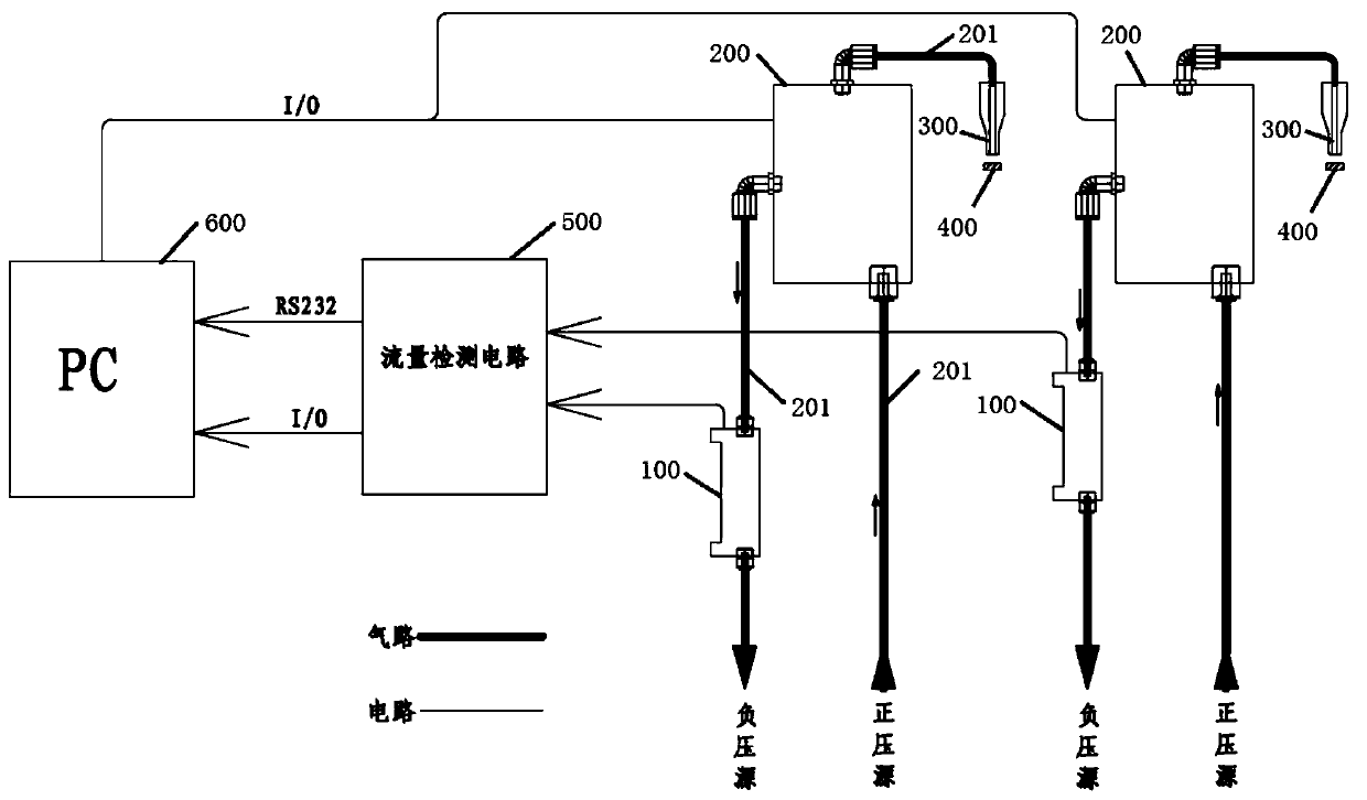
[0062] Please refer to figure 1 , The reclaiming equipment of the solid crystal machine includes a reclaiming device.

[0063] The material taking device inc...


PUM


Abstract

The invention discloses a method for finely detecting the working state of a suction nozzle. The method comprises the following steps: a flow detection circuit acquires a preset comparison voltage of the suction nozzle from an upper computer; the flow detection circuit judges whether a working voltage is larger than or equal to the comparison voltage or not; if so, the flow detection circuit judges that the suction nozzle works normally, and informs the upper computer that the suction nozzle works normally at present; otherwise, the flow detection circuit judges that the nozzle works abnormally, and informs the upper computer that the suction nozzle works abnormally at present. Voltage sampling can be performed through a lower computer, and a sampled working voltage is compared with the comparison voltage which is transmitted to the lower computer by the upper computer in order to judge the state of the suction nozzle; when the suction nozzle can still be used after being aged, the value of the comparison voltage can be changed, so that the service life of the suction nozzle is prolonged equivalently; moreover, a comparison result of the suction nozzle can be obtained by the upper computer in real time, so that management and control of equipment are facilitated, and the state of the suction nozzle can be judged efficiently and smartly.

Description

technical field [0001] The invention relates to the technical field of crystal bonding machines, in particular to a method for finely detecting the working state of a suction nozzle. Background technique [0002] The state detection of the suction nozzle is highly required in the reclaiming process of the die bonder. How to judge the state of the suction nozzle efficiently and intelligently is particularly important. Moreover, with the continuous improvement of equipment management and control requirements, it is necessary to control the working conditions of each equipment through a host computer. [0003] At present, the state detection of the suction nozzle in the market mainly uses the analog voltage value fed back by the flow sensor in the suction nozzle, and compares the analog voltage fed back by the sensor with the comparison voltage composed of a potentiometer and a resistor, and then judges the working state of the suction nozzle, and the The value of the comparis...

Claims


Application Information

Patent Timeline
Patent Type & Authority Patents(China)
IPC IPC(8): G01M13/00G01F1/60
CPCG01F1/60G01M13/00
Inventor 邱国良
Owner GKG PRECISION MACHINE
Why Eureka
Try Eureka