
Light guide plate, backlight module and display device

A technology of backlight module and light guide plate, applied in the direction of light guide, optics, optical components, etc., can solve the problem of uneven brightness, and achieve the effect of improving brightness uniformity and improving brightness and darkness.

Active Publication Date: 2020-04-03
RADIANT OPTO ELECTRONICS SUZHOU +1
View PDF5 Cites 0 Cited by
  • Summary
  • Abstract
  • Description
  • Claims
  • Application Information

AI Technical Summary

Problems solved by technology

[0004] Therefore, an object of the present invention is to provide a light guide plate, a backlight module and a display device, which can improve the problem of uneven brightness of the light guide plate near the light-incident surface, and can improve the uniformity of the light appearance of the overall backlight module

Method used


Image

  • Light guide plate, backlight module and display device
  • Light guide plate, backlight module and display device
  • Light guide plate, backlight module and display device

Examples


Embodiment Construction

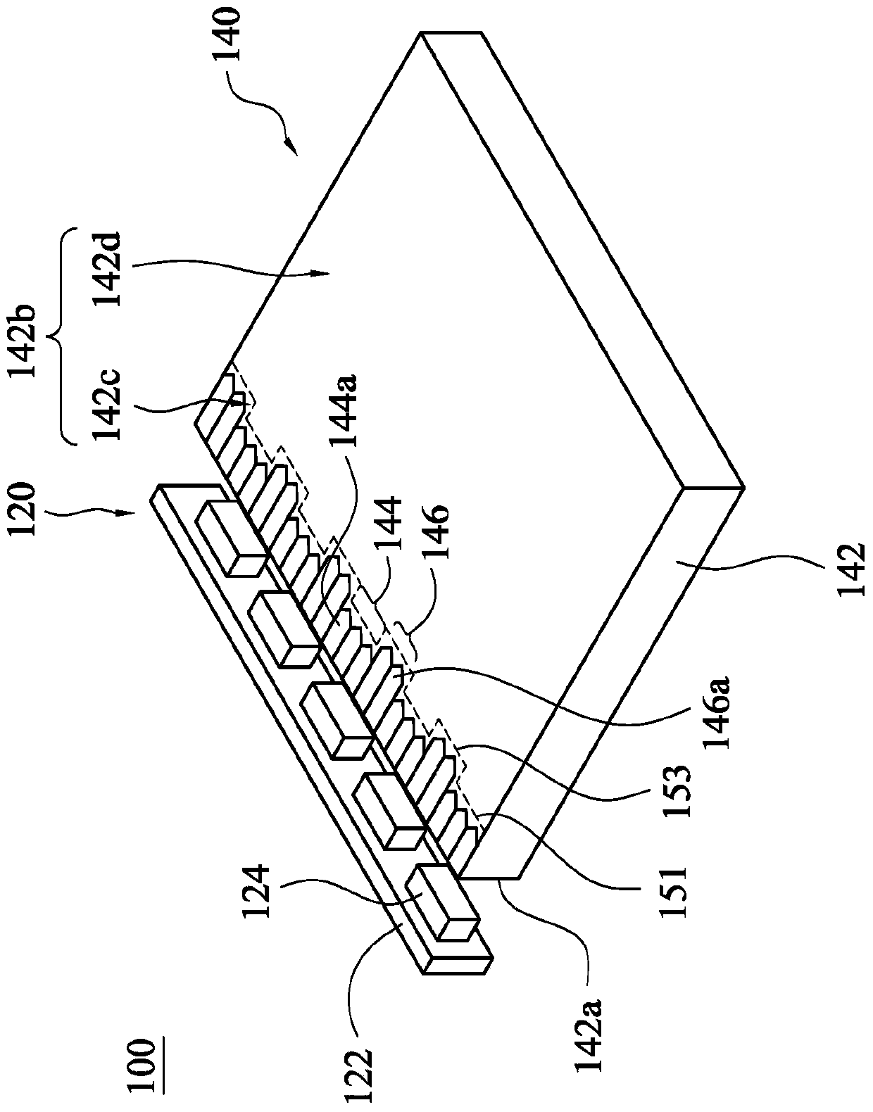
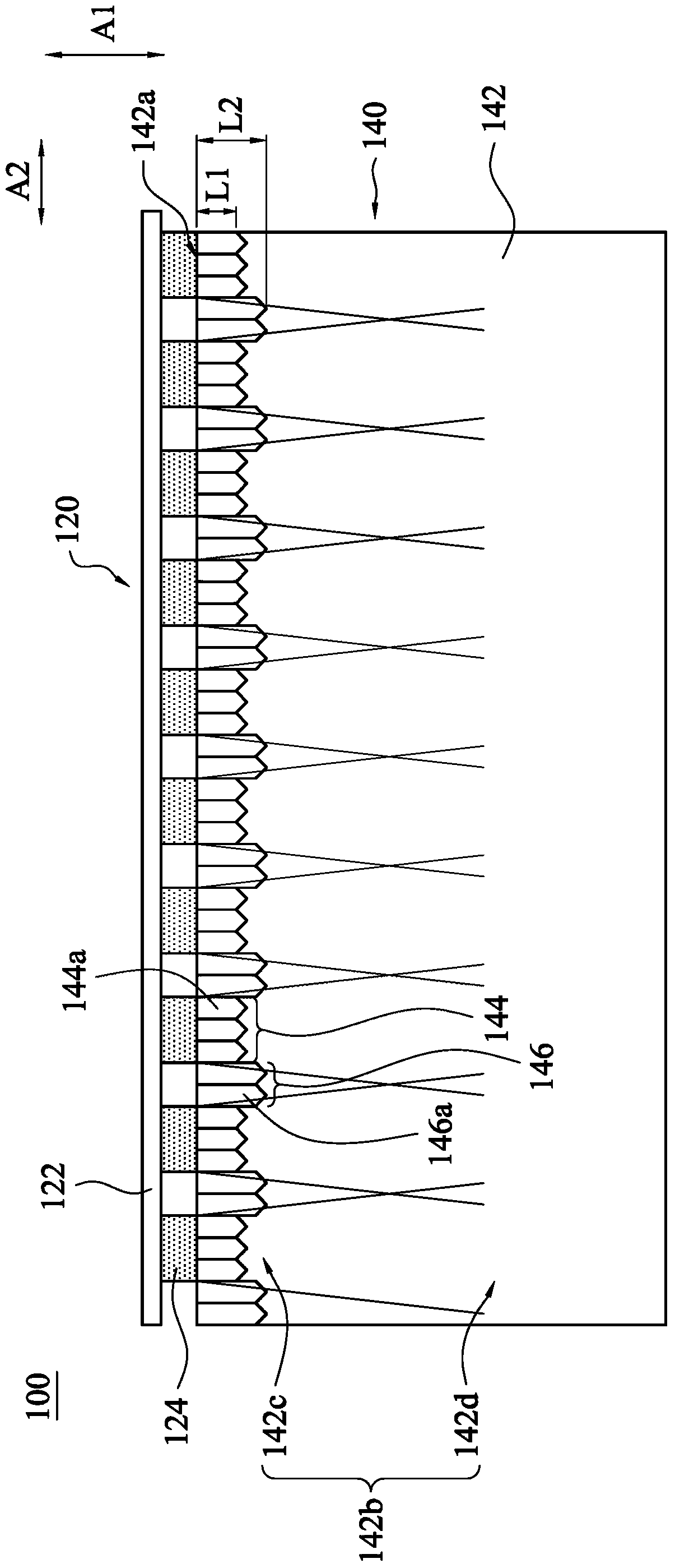
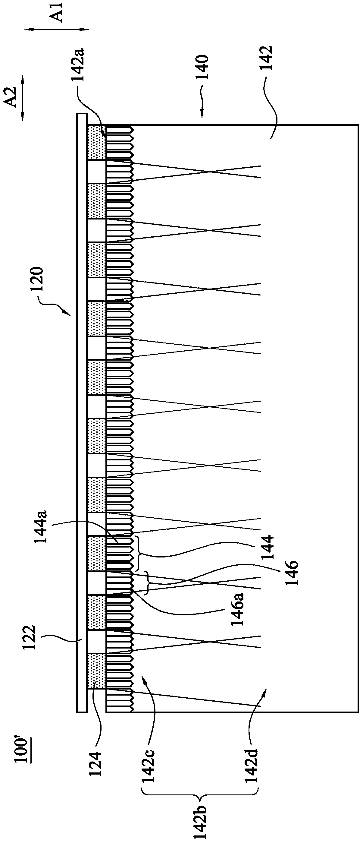
[0041] Also refer to Figure 1A and Figure 1B , which are respectively a device schematic diagram and a top view describing a backlight module according to the first embodiment of the present invention. The backlight module 100 of this embodiment mainly includes a light source 120 and a light guide plate 140 . The light guide plate 140 mainly includes a main body 142 , a plurality of first microstructure regions 144 and a plurality of second microstructure regions 146 . The first microstructure region 144 and the second microstructure region 146 are disposed on the main body 142, and through the first microstructure region 144 and the second microstructure region 146, the light leakage of the light guide plate 140 close to the light incident can be effectively atomized, and the The phenomenon of uneven brightness and darkness near the light incident can be greatly improved, thereby improving the brightness uniformity of the overall backlight module 100 .

[0042] Continue t...


PUM


Abstract

A light guide plate, a backlight module and a display device are provided. The light guide plate includes a main body, plural first microstructure portions and plural second microstructure portions. The main body includes a light-incident surface and an optical surface. The light-incident surface is connected to the optical surface, and the optical surface includes a first area. The first microstructure portions are disposed on the first area of the optical surface. The second microstructure portions are disposed on the first area of the optical surface, in which the second microstructure portions and the first microstructure portions are alternately arranged and aligned with each other, and the first microstructure portions are different from the second microstructure portions.

Description

technical field [0001] The invention relates to a light guide assembly and its application, in particular to a light guide plate and the application of the light guide plate in a backlight module and a display device. Background technique [0002] A known backlight module mainly includes a light bar and a light guide plate. The light bar includes a circuit board and the light emitting diodes are arranged on the surface of the circuit board. in. The light guide plate is arranged beside the light emitting diode, and the light incident surface of the light guide plate is attached to the light emitting surface of the light emitting diode, so that the light of the light emitting diode can be effectively used. [0003] However, since the light incident surface of the light guide plate is attached to the light output surface of the light emitting diodes, bright bands or uneven brightness are likely to appear on the part of the light guide plate close to the light emitting diodes,...

Claims


Application Information

Patent Timeline
Patent Type & Authority Patents(China)
IPC IPC(8): G02B6/00
CPCG02B6/0016G02B6/002G02B6/0068
Inventor 张嘉尹翁巾婷黄柏菖林信伯李岳衡
Owner RADIANT OPTO ELECTRONICS SUZHOU
Learn More