Optical module shell temperature monitoring method and device

A technology of optical module and shell temperature, which is applied in the field of communication and can solve problems such as deviation of monitoring accuracy

Active Publication Date: 2017-05-31
HISENSE BROADBAND MULTIMEDIA TECH
View PDF5 Cites 6 Cited by
  • Summary
  • Abstract
  • Description
  • Claims
  • Application Information

AI Technical Summary

Problems solved by technology

[0005] The invention provides a method and device for monitoring the housing temperature of an optical module, which is used to solve the technical problem that there is a large devi

Method used


Image

  • Optical module shell temperature monitoring method and device
  • Optical module shell temperature monitoring method and device
  • Optical module shell temperature monitoring method and device

Examples


Embodiment Construction

[0023] In order to make the technical problems, technical solutions and effects solved by the present invention clearer, the preferred embodiments of the present invention will be described below in conjunction with the accompanying drawings. It should be understood that the preferred embodiments described here are only used to illustrate and explain the present invention. Invention is not intended to limit the present invention. And in the case of no conflict, the embodiments in the present application and the features in the embodiments can be combined with each other.

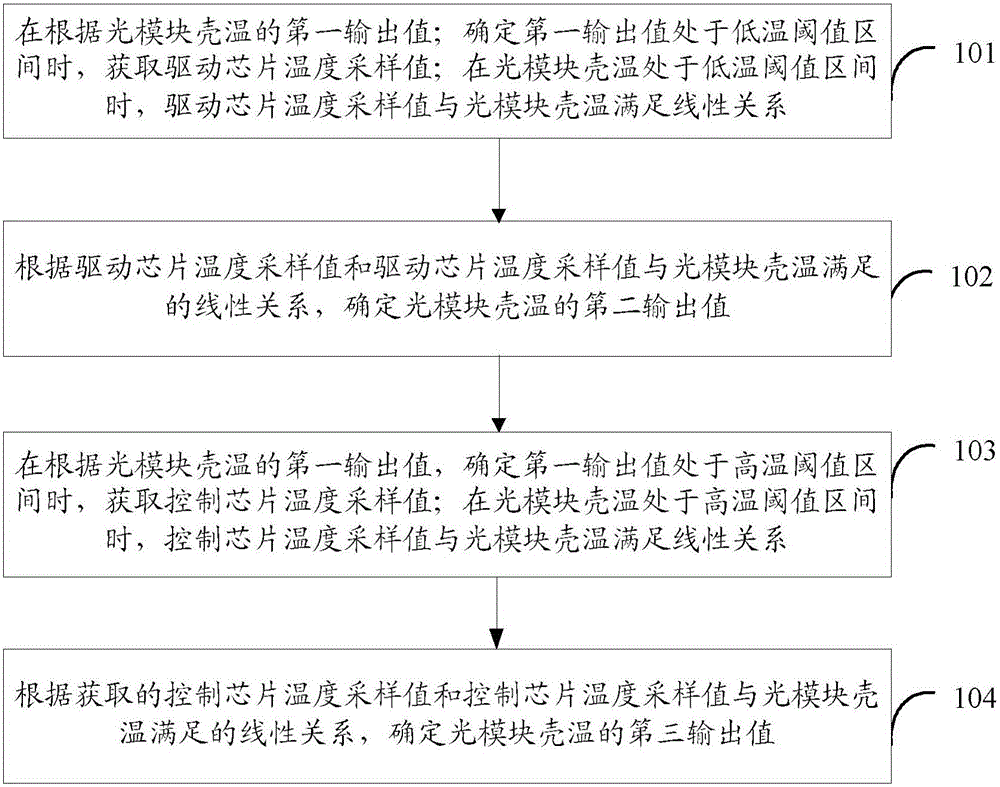
[0024] First of all, it is worth noting that the housing temperature of the optical module in the embodiment of the present invention represents the temperature of the housing of the optical module, and the housing temperature of the optical module is affected by the ambient temperature of the optical module. Usually, the housing temperature of the optical module is obtained by linearly compensating the tempe...


PUM


Abstract

The invention discloses an optical module shell temperature monitoring method and device for improving the monitoring accuracy of the shell temperature of an optical module in each temperature range. The method comprises a step of obtaining a driving chip temperature sampling value when a condition that a first output value is in a low temperature threshold interval is determined according to a first output value of optical module shell temperature, a step of determining the second output value of the optical module shell temperature according to the linear relationship satisfied by the driving chip temperature sampling value and the optical module shell temperature, a step of obtaining a control chip temperature sampling value when a condition that the second output value is in a high temperature threshold interval is determined according to the second output value of the optical module shell temperature, and a step of determining the third output value of the optical module shell temperature according to the linear relationship satisfied by the control chip temperature sampling value and the optical module shell temperature. Different temperature sampling sources are selected to monitor the optical module shell temperature in different temperature ranges, and the monitoring accuracy of the optical module shell temperature in each temperature range is improved.

Description

technical field [0001] Embodiments of the present invention relate to the field of communication technologies, and in particular, to a method and device for monitoring the housing temperature of an optical module. Background technique [0002] In recent years, with the rapid development of the communication industry, more and more communication devices are used in increasingly harsh natural environments, and extreme weather conditions have continuously increased the requirements for the temperature adaptability of communication devices. Accurate temperature monitoring can better reflect the current working conditions of the optical module, and provide a more accurate temperature reference for the adaptive adjustment of the optical module. It can also timely issue temperature alarms for over-temperature applications, trigger equipment protection function circuits, and prevent irreversible damage to equipment caused by over-temperature applications. [0003] However, at prese...

Claims


Application Information

Patent Timeline
IPC IPC(8): G05D23/20
CPCG05D23/20
Inventor 崔涛
Owner HISENSE BROADBAND MULTIMEDIA TECH
Why Eureka
Try Eureka