An optical power monitoring circuit and method

A technology of optical power monitoring and optical power, which is applied in the field of optical communication, can solve the problems of increasing the design complexity and production cost of the optical power monitoring and reporting circuit of the optical module

Active Publication Date: 2020-10-23
GUANGXUN SCI & TECH WUHAN +1
View PDF8 Cites 0 Cited by
  • Summary
  • Abstract
  • Description
  • Claims
  • Application Information

AI Technical Summary

Problems solved by technology

[0003] However, adding photodiodes and their bypass gold wires will increase the design complexit

Method used


Image

  • An optical power monitoring circuit and method
  • An optical power monitoring circuit and method
  • An optical power monitoring circuit and method

Examples


Embodiment Construction

[0032] The present invention will be described in further detail below in conjunction with the accompanying drawings and embodiments. It should be understood that the specific embodiments described here are only used to explain the present invention, not to limit the present invention.

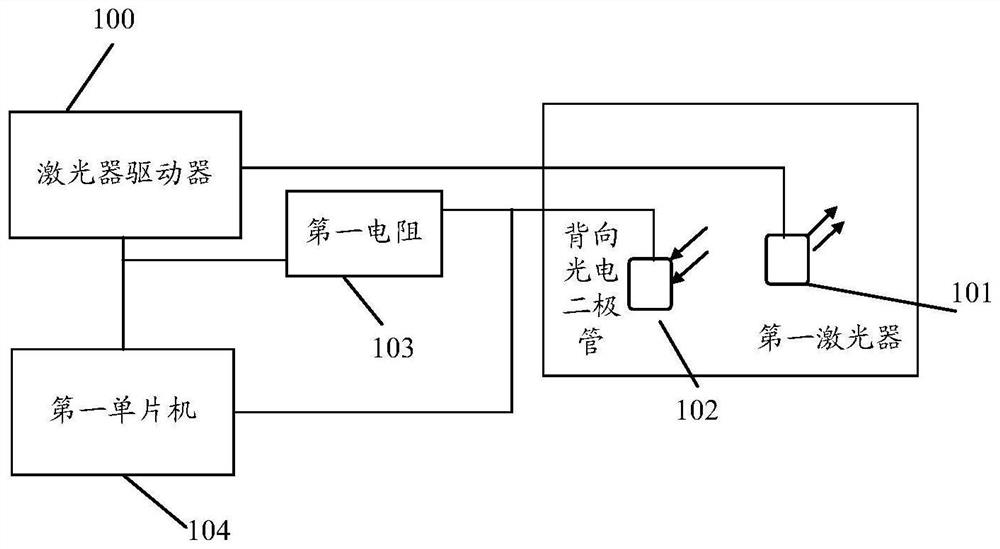
[0033] The optical power monitoring circuit proposed in the embodiment of the present invention can monitor the optical power of the optical module transmitter; here, the optical module (optical module) can be composed of an optoelectronic device, a functional circuit and an optical interface, etc., and the optoelectronic device includes two parts: transmitting and receiving . The function of the optical module is to perform photoelectric conversion. The transmitting end converts the electrical signal into an optical signal. After transmission through the optical fiber, the receiving end converts the optical signal into an electrical signal.

[0034] Among them, in the optical module transmit...


PUM


Abstract

The embodiment of the invention provides an optical power monitoring circuit and method. The optical power monitoring circuit comprises a driving device, a light emitting device and a processing device, wherein the driving device is used for driving the light-emitting device to emit light, the processing device is used for obtaining node current or node voltage, the node current represents the current of a node between the light-emitting device and the driving device, and the node voltage represents the voltage of the node between the light-emitting device and the driving device; and the processing device is used for determining the optical power of the light emitting device based on the node current or the node voltage. Thus, the optical power of the light-emitting device in the optical power monitoring circuit can be monitored without adding a photodiode and a bypass gold wire bonding wire thereof, and the design complexity and the manufacturing cost of the optical power monitoring circuit are effectively reduced.

Description

technical field [0001] The invention relates to the technical field of optical communication, in particular to an optical power monitoring circuit and method. Background technique [0002] In the related art, for the optical power monitoring and reporting circuit of the optical module, when the laser driver drives the laser (Laser Diode, LD) to emit light, it is usually necessary to add a backside monitoring photodiode (Monitor Photo-Diode, MPD) and its bypass gold wire Line to generate photo-generated current, and then sample the voltage of the sampling resistor through the microcontroller to obtain the sampled voltage value, based on the resistance value of the sampling resistor and the sampled voltage value, determine the photo-generated current generated by the photodiode. According to the linear proportional relationship between the photogenerated current and the optical power, the monitoring and reporting of the optical power of the laser is realized. [0003] However...

Claims


Application Information

Patent Timeline
IPC IPC(8): H04B10/079G01J1/44
CPCH04B10/07955G01J1/44
Inventor 林韬陈春山张武平王飚
Owner GUANGXUN SCI & TECH WUHAN
Why Eureka
Try Eureka