
Gas density relay

A gas density and relay technology, applied in the direction of circuits, electric switches, electrical components, etc., can solve the problems of sulfur hexafluoride gas density relays that cannot work normally, malfunction, and poor precision

Pending Publication Date: 2020-06-23
SHANGHAI ROYE ELECTRICAL CO LTD
View PDF0 Cites 2 Cited by
  • Summary
  • Abstract
  • Description
  • Claims
  • Application Information

AI Technical Summary

Problems solved by technology

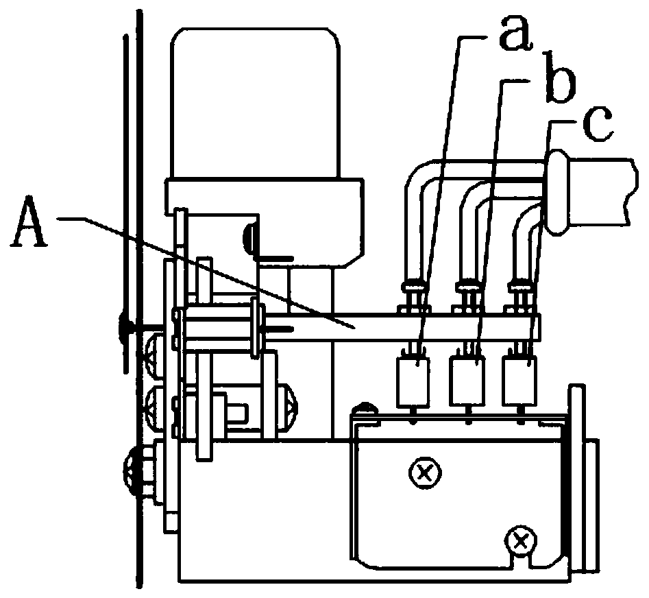
Although the gas density relay with this structure has the advantages of good electrical performance, because the length of the contact operation arm A is long and it is a cantilever beam, the very small vibration in the working environment may cause the contact operation arm A to vibrate very much. Large, causing the sulfur hexafluoride gas density relay to malfunction, or even destroy the micro switch, resulting in the sulfur hexafluoride gas density relay not working properly
Another kind of density relay that uses a bellows to monitor the gas density has the problem of large swing of the trigger rod movement, which is not suitable for control and poor precision.
[0003] Therefore, how to change the status quo of poor anti-vibration performance and poor precision of gas density relays in the prior art has become a technical problem urgently needed to be solved by those skilled in the art

Method used


Image

  • Gas density relay
  • Gas density relay
  • Gas density relay

Examples


Embodiment Construction

[0024] The following will clearly and completely describe the technical solutions in the embodiments of the present invention with reference to the accompanying drawings in the embodiments of the present invention. Obviously, the described embodiments are only some, not all, embodiments of the present invention. Based on the embodiments of the present invention, all other embodiments obtained by persons of ordinary skill in the art without making creative efforts belong to the protection scope of the present invention.

[0025] The object of the present invention is to provide a gas density relay to solve the above-mentioned problems in the prior art and improve the anti-vibration performance and monitoring accuracy of the gas density relay.

[0026] In order to make the above objects, features and advantages of the present invention more comprehensible, the present invention will be further described in detail below in conjunction with the accompanying drawings and specific em...


PUM


Abstract

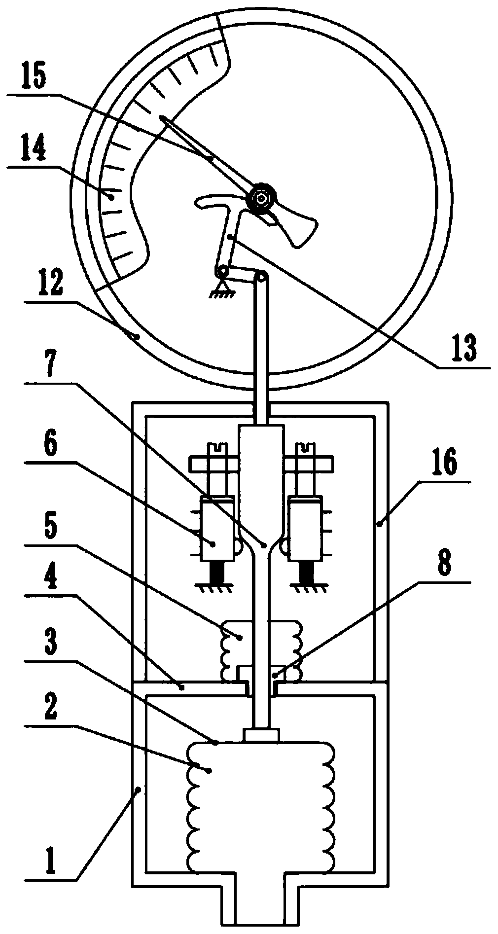
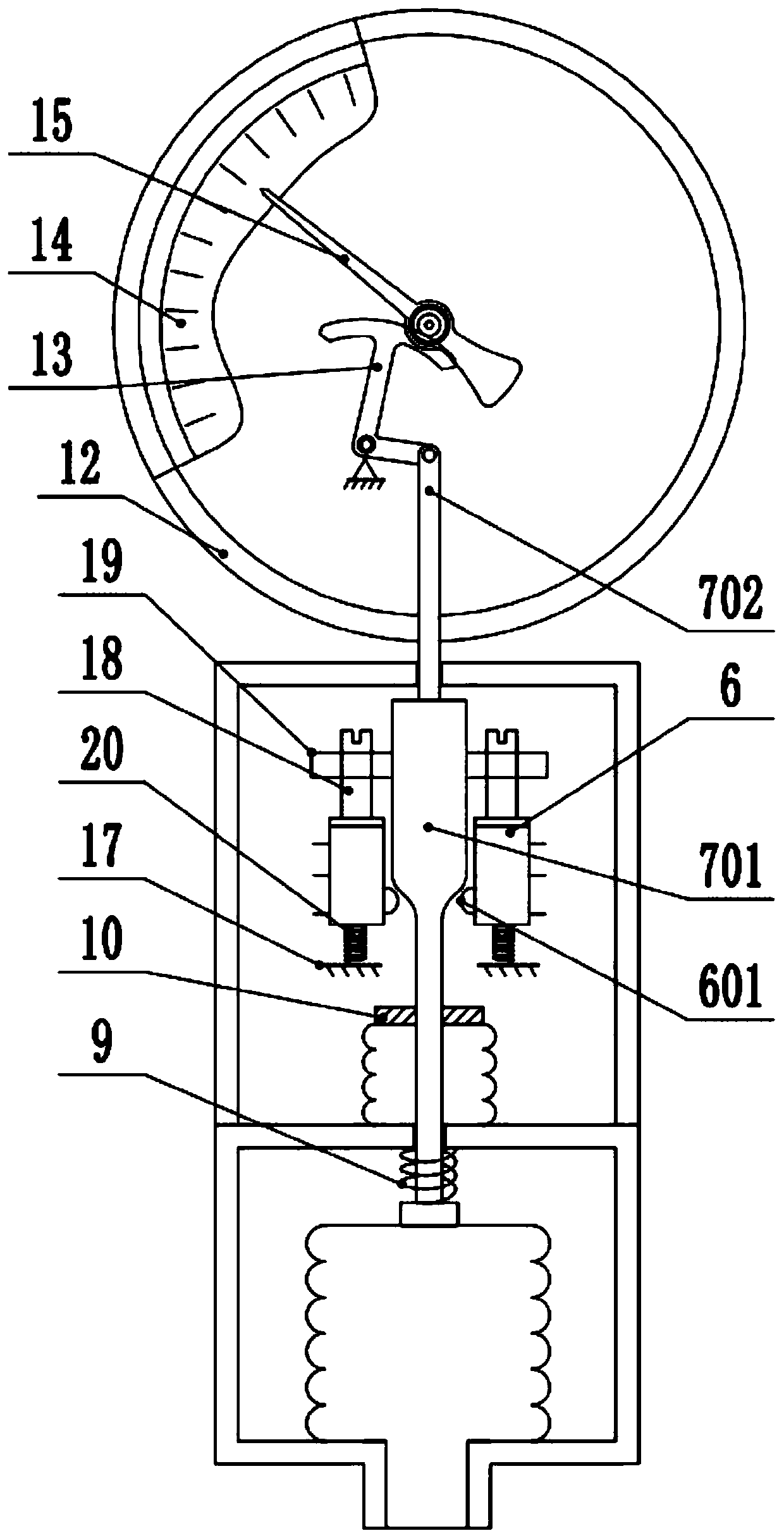
The invention discloses a gas density relay. The gas density relay comprises an outer shell, a corrugated pipe, a sealing piece, a sealing partition plate, a plugging corrugated pipe, a signal triggering mechanism and a contact microswitch. An inner cavity of the outer shell or an inner cavity of the corrugated pipe is communicated with an air chamber of electrical equipment, and a compensation gas is filled in the other inner cavity; and when the gas density value in the gas chamber of the electrical equipment is changed, a pressure difference is generated between an inner cavity of the outershell and an inner cavity of the corrugated pipe, under the action of pressure, the corrugated pipe can expand or be compressed, the corrugated pipe moves up and down to drive the trigger rod connected with the corrugated pipe to move up and down, the trigger rod triggers the contact microswitch when moving, the contact microswitch generates corresponding signals, and the function of the gas density relay is achieved. And when the gas density value returns to normal, the contact microswitch is reset. The trigger rod is slidably connected with the sealing partition plate and extends out of thesealing partition plate, the motion stability of the trigger rod is improved, and the problem that the monitoring precision is reduced due to swing of the trigger rod is avoided.

Description

technical field [0001] The invention relates to the technical field of electric equipment and its peripheral supporting facilities, in particular to a gas density relay. Background technique [0002] At present, a gas density relay whose contact is a micro switch is usually used to monitor the density of the insulating gas in the gas-insulated equipment. figure 1 It is a structural schematic diagram of an existing sulfur hexafluoride gas density relay, such as figure 1 As shown, the microswitches used in this sulfur hexafluoride gas density relay are equipped with operating arm a, operating arm b and operating arm c, and operating arm a, operating arm b and operating arm c can be connected with the corresponding signal The adjustment mechanism is in contact. Although the gas density relay with this structure has the advantages of good electrical performance, but because the contact operating arm A is long in length and belongs to the cantilever beam, the very small vibrati...

Claims


Application Information

Patent Timeline
Patent Type & Authority Applications(China)
IPC IPC(8): H01H35/32H01H35/26
CPCH01H35/26H01H35/32
Inventor 张雪珺常敏金海勇王恩林
Owner SHANGHAI ROYE ELECTRICAL CO LTD
Learn More