Heat dissipation device and combined heat dissipation device

A technology of heat dissipation device and drive structure, which is used in instruments, electrical digital data processing, digital data processing parts, etc. The fan is not easy to customize and other problems, to achieve the effect of simple structure, long service life, simple disassembly and installation

Pending Publication Date: 2017-05-31
TANGSHAN DACHUANG TECH CO LTD
View PDF7 Cites 1 Cited by
  • Summary
  • Abstract
  • Description
  • Claims
  • Application Information

AI Technical Summary

Problems solved by technology

However, common cooling fans in the market are fixed in several sizes. For heating elements of different sizes, the cooling fan cannot correspond to the size of all heating elements, so that the part of the heating element cannot become the effective cooling range of the cooling fan. In other words, the heat dissipation The fan is not easy to customize
[0003] Further

Method used


Image

  • Heat dissipation device and combined heat dissipation device
  • Heat dissipation device and combined heat dissipation device
  • Heat dissipation device and combined heat dissipation device

Examples


Embodiment 1

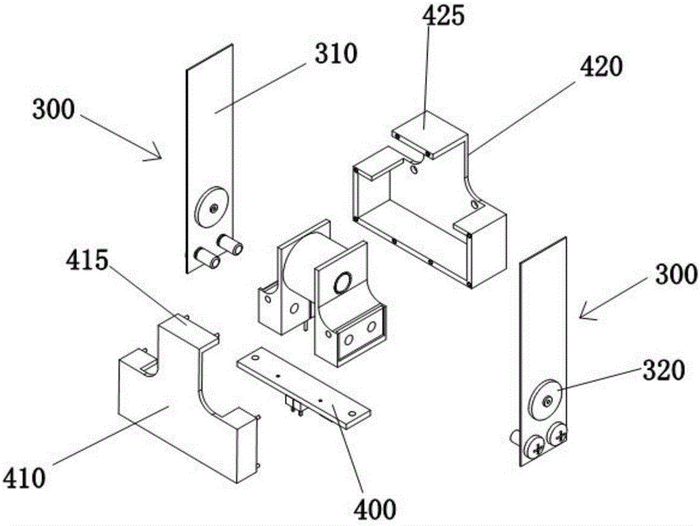
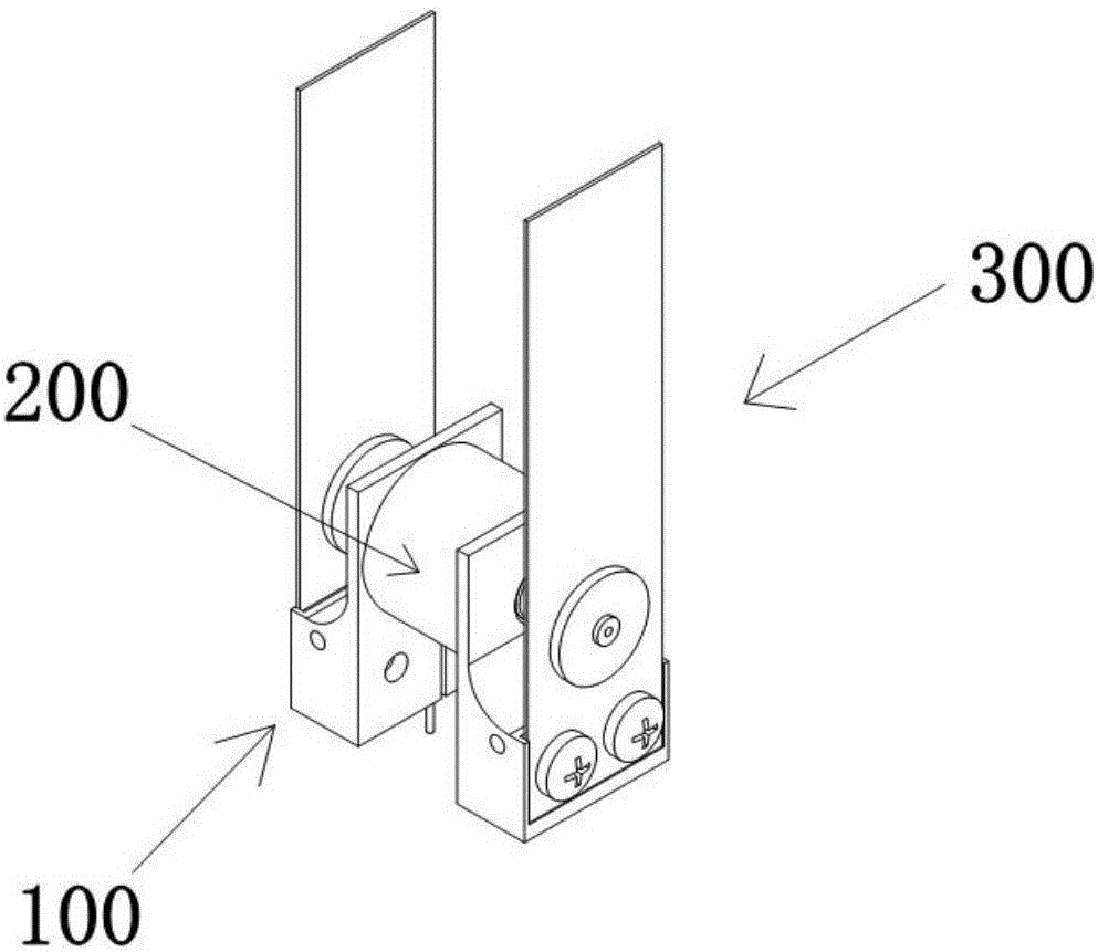
[0031] Such as Figure 1 to Figure 5 As shown, the heat dissipation device provided by the present invention includes a base 100, a driving structure 200 capable of generating a periodic magnetic field, and at least one swinging structure 300. The driving structure 200 is installed on the base 100 for adjusting the swinging frequency of the swinging structure 300. The frequency adjustment module 400 is electrically connected to the drive structure 200, the frequency adjustment module 400 is connected to an external power supply, the fixed end of the swing structure 300 is installed on the base 100, and the swing structure 300 is opposite to the magnetic pole of the drive structure 200, and the free end of the swing structure 300 is driven Under the action of the structure 200, it swings back and forth.

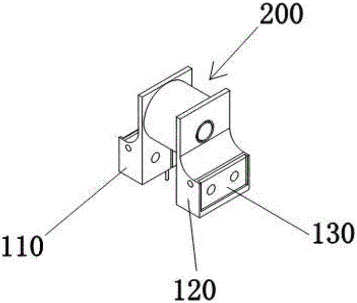
[0032] As a possible implementation manner, the base 100 includes a first base 110 and a second base 120 , and the first base 110 and the second base 120 are both provided wit...

Embodiment 2

[0041] On the basis of Embodiment 1, the present invention also provides a combined heat dissipation device, which also includes a housing, wherein there are multiple bases 100, driving structures 200 and swing structures 300, and a plurality of In the cavity containing the driving structure 200 and the base 100, a plurality of driving structures 200 and the base 100 are sequentially installed in the inner cavity, the iron cores 210 of the multiple driving structures 200 are coaxial, and the magnetic pole directions of adjacent driving structures 200 are opposite , a plurality of drive structures 200 are electrically connected to the frequency adjustment module 400, fixed ends of a plurality of swing structures 300 are sequentially installed between adjacent drive structures 200, and free ends of the swing structures 300 are driven by the drive structure 200 to swing back and forth.

[0042] The present invention adopts the above technical scheme, and the technical effect achie...


PUM


Abstract

The invention discloses a heat dissipation device and a combined heat dissipation device. The heat dissipation device comprises a base, a driving structure which is capable of producing a periodic magnetic field and at least one swinging structure, wherein the driving structure is installed on the base, a frequency adjusting module which is used for adjusting the swinging frequency of the swinging structure is electrically connected with the driving structure, the frequency adjusting module is externally connected to a power source, the fixed end of the swinging structure is installed on the base, the magnetic pole of the swinging structure is relative to the magnetic pole of the driving structure, and the free end of the swinging structure conducts reciprocating swinging under the action of the driving structure. The heat dissipation device is simple in structure, convenient to use, longer in service life and better in air output effect, and has very high practicability.

Description

technical field [0001] The invention relates to a heat dissipation device and a combined heat dissipation device. Background technique [0002] With the rapid development of electronic products, whether it is a notebook computer, a desktop computer or a tablet computer, the performance of electronic components such as the central processing unit has been greatly improved compared with the past. If the space remains the same, or tends to shrink, the calorific value per unit area of ​​the electronic components in the calculation will increase accordingly. If the heat cannot be effectively removed, the excessively high temperature will have a considerable impact on the operation of the electronic components. Electronic components are referred to below as heating elements, which will cause the so-called "heating". The existing method of reducing "heating" is to install a cooling fan for the heating element to reduce the temperature of the heat dissipation environment of the heat...

Claims


Application Information

Patent Timeline
IPC IPC(8): G06F1/20
CPCG06F1/20
Inventor 任毅恒徐韩洋苏献钦
Owner TANGSHAN DACHUANG TECH CO LTD
Why Eureka
Try Eureka