
Layout method of turbine blade precision-cast wax-mold ceramic core clamping element

A technology for clamping components and turbine blades, which is applied in the direction of genetic models, genetic rules, and special data processing applications, can solve problems such as motion drift, wax model wall thickness deviation, etc., to speed up the work process and improve search efficiency. Effect

Active Publication Date: 2017-05-31
SHANGHAI BLAN ELECTRONICS TECH
View PDF5 Cites 6 Cited by
  • Summary
  • Abstract
  • Description
  • Claims
  • Application Information

AI Technical Summary

Problems solved by technology

It is precisely because of the existence of this gap that when the wax fills the cavity, the ceramic core is prone to motion drift in a small space due to the influence of the wax flow, thus causing the wall thickness deviation of the wax model.

Method used


Image

  • Layout method of turbine blade precision-cast wax-mold ceramic core clamping element
  • Layout method of turbine blade precision-cast wax-mold ceramic core clamping element
  • Layout method of turbine blade precision-cast wax-mold ceramic core clamping element

Examples


Embodiment Construction

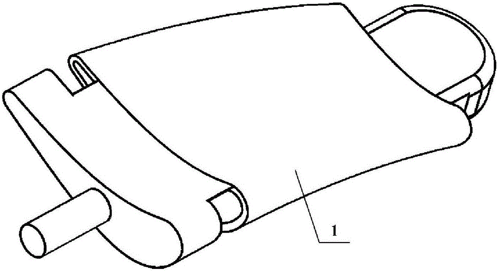
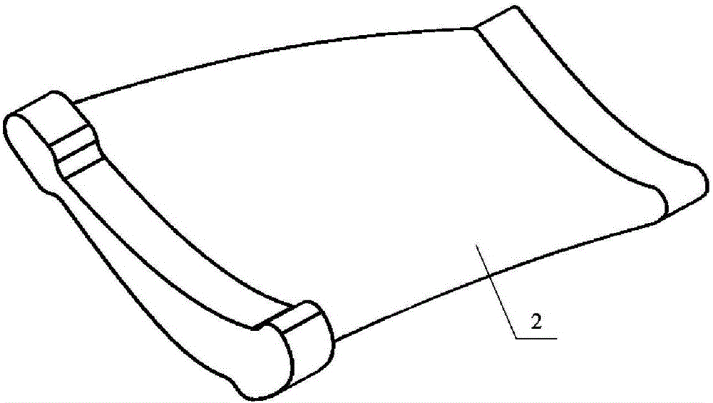
[0040] In order to more clearly illustrate the embodiments of the present invention or the technical solutions in the prior art, the specific implementation manners of the present invention will be described below with reference to the accompanying drawings. Obviously, the accompanying drawings in the following description are only some embodiments of the present invention, and those skilled in the art can obtain other accompanying drawings based on these drawings and obtain other implementations.

[0041] In order to make the drawing concise, each drawing only schematically shows the parts related to the present invention, and they do not represent the actual structure of the product. In addition, to make the drawings concise and easy to understand, in some drawings, only one of the components having the same structure or function is schematically shown, or only one of them is marked. Herein, "a" not only means "only one", but also means "more than one".

[0042] The presen...


PUM


Abstract

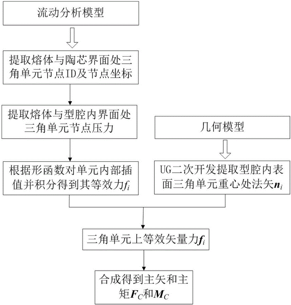
The invention discloses a layout method of a turbine blade precision-cast wax-mold ceramic core clamping element. The layout method comprises the following steps that S10, flow simulation analysis is conducted on wax-mold filling process; S20, the dynamic change situation of ceramic stress in the wax-mold filling process is calculated through injection molding simulation; S30, a dynamic drifting displacement field of a ceramic core under the effects of gravity, a first contact collision force, a second contact collision force, a wax material flow acting force and a force moment is calculated through motion simulation; S40, a plurality of monitoring points are selected from the positions of cross sections of blade tips and blade roots of the ceramic core, and position vectors of the multiple monitoring points are obtained in the dynamic drifting displacement field established in the step S30, wherein the displacement of each monitoring point is the difference of the position vectors before and after wax-mold filling process, and the sum of the displacements of the monitoring points is the motion drifting indicating amount of the ceramic core; clamping element layout corresponding to the smallest motion drifting indicating amount is found through a genetic algorithm.

Description

technical field [0001] The invention relates to the technical field of wax mold filling, in particular to a method for laying out the clamping elements of a precision-cast wax-type ceramic core for turbine blades. Background technique [0002] At present, hollow turbine blades are usually prepared by investment casting. In this preparation method, a ceramic core is usually placed in a mold to prepare a hollow wax mold, and a hollow blade with an inner cavity surface is formed through the steps of shell making, dewaxing, pouring, shelling and core removal. The wall thickness between the inner and outer profiles of the hollow turbine blade is an important index to ensure its strength and cooling efficiency, and is also an important parameter to ensure its service life. Research on the causes of failure of different types of turbine blades by relevant scholars shows that "wall thickness" is one of the most important reasons for blade failure. Therefore, ensuring that the wall...

Claims


Application Information

Patent Timeline
Patent Type & Authority Applications(China)
IPC IPC(8): G06F17/50G06N3/12
CPCG06F30/23G06N3/126
Inventor 朱金焰
Owner SHANGHAI BLAN ELECTRONICS TECH
Learn More