
Test device for dense environmental performance of RFID (radiofrequency identification) systems and method for operating test device

A technology of dense environment and test device, applied in the field of RFID reader working ability test, it can solve problems such as affecting the accuracy of test results and changing antenna distribution.

Inactive Publication Date: 2017-05-31
SHANDONG UNIV
View PDF6 Cites 9 Cited by
  • Summary
  • Abstract
  • Description
  • Claims
  • Application Information

AI Technical Summary

Problems solved by technology

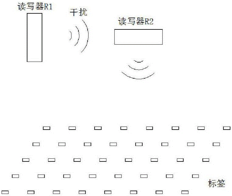
[0010] The setting of the test site should ensure that external interference is minimized. For example, there should be no equipment that emits electromagnetic signals nearby, and metal products that are not related to the test should be avoided in the test site, because they have a greater impact on the signal sent by the antenna and may change the antenna. The distribution of electromagnetic waves is emitted, which in turn affects the accuracy of test results

Method used


Image

  • Test device for dense environmental performance of RFID (radiofrequency identification) systems and method for operating test device
  • Test device for dense environmental performance of RFID (radiofrequency identification) systems and method for operating test device
  • Test device for dense environmental performance of RFID (radiofrequency identification) systems and method for operating test device

Examples


Embodiment 1

[0075] Such as Figure 4 shown.

[0076] A test device for the performance of an RFID system in a dense environment, including a horizontal guide rail 2 arranged in a test environment, a first reader antenna 8, a second reader antenna 9, a tag array 10, and a computer 3 and a switch arranged outside the test environment 4. The first reader to be tested 5, the second reader to be tested 6; the first reader antenna 8 and the second reader antenna 9 are respectively slidably arranged on the horizontal guide rail 2; the first reader antenna 8 passes through the first The reader 5 to be tested and the switch 4 are connected to the computer 3; the second reader antenna 9 is connected to the computer 3 through the second reader 6 to be tested and the switch 4 in turn; the label array 10 is arranged directly below the horizontal guide rail 2.

Embodiment 2

[0078] The device for testing the performance of the RFID system in a dense environment as described in Embodiment 1, the difference is that the test environment is a fully anechoic chamber. The full anechoic chamber is a structure equipped with absorbing materials on six sides, which can simulate free space very well and overcome the shortcomings of the half anechoic chamber.

Embodiment 3

[0080] The difference is that the first reader antenna 8 and the second reader antenna 9 are respectively arranged on the horizontal guide rail 2 by sliding on the guide rail slider. The distance between the reader antennas can be changed by controlling the position of the slider on the guide rail through the computer 3 .


PUM


Abstract

The invention relates to a test device for the dense environmental performance of RFID (radiofrequency identification) systems and a method for operating the test device. The test device comprises a horizontal guide rail, a first reader antenna, a second reader antenna, a tag array, a computer, a switchboard, a first to-be-tested reader and a second to-be-tested reader. The horizontal guide rail, the first reader antenna, the second reader antenna and the tag array are arranged in a test environment, and the computer, the switchboard, the first to-be-tested reader and the second to-be-tested reader are arranged outside the test environment. The test device for the dense environmental performance of the RFID systems and the method have the advantages that evaluation standards for the performance of the RFID systems in dense laying environments are proposed for the first time and can be used for comparing the difference of the dense environmental performance of readers in the market; selection of models of the readers and laying position designs can be guided when the RFID systems in dense environments are designed.

Description

technical field [0001] The invention relates to a device for testing the performance of an RFID system in a dense environment and a working method thereof, and belongs to the technical field of the working ability test of an RFID reader. Background technique [0002] RFID (Radio Frequency Identification) is a non-contact automatic identification technology realized by radio frequency reflection technology. Due to the characteristics of RFID tags such as small size, low cost, long service life, and high security, RFID technology has been widely used in logistics, manufacturing, charging, and personnel authorization management in recent years, greatly improving management and operational efficiency. [0003] With the increase of RFID application scenarios, the application scenarios have higher and higher requirements on the performance of RFID systems. Now, more and more application scenarios need to densely deploy multiple readers and a large number of tags in one place, whi...

Claims


Application Information

Patent Timeline
Patent Type & Authority Applications(China)
IPC IPC(8): G06K17/00G06K7/10
CPCG06K17/0032G06K7/10019
Inventor 王洪君王露许建华马良杨阳
Owner SHANDONG UNIV
Learn More