Deep Sea Broadband Mosaic Ring Transducer

A transducer and ring technology, which is applied in the field of deep-sea broadband inlaid ring transducers, can solve the problems of reducing the maximum radiation capacity of the transducer, reducing reliability, sensitivity and convenience, and heavy transducer weight. Reduced weight and manufacturing complexity, light weight, high electro-acoustic efficiency

Active Publication Date: 2020-06-16
HARBIN ENG UNIV
View PDF14 Cites 0 Cited by
  • Summary
  • Abstract
  • Description
  • Claims
  • Application Information

AI Technical Summary

Problems solved by technology

The above three forms have certain shortcomings in the actual application process. The overflow type of polyurethane rubber vulcanization makes the coupling coefficient between the ceramic ring and water decrease during the vibration process, thereby reducing the maximum radiation capacity of the transducer; pressure The compensation form generally has a compressor with a complex structure and requires an accurate feedback system. In the actual engineering application process, the reliability and sensitivity and convenience are greatly reduced; the traditional oil-filled structure is that the rubber bladder is completely covered with ceramics. Ring, and there is a great contradiction between the structural size (weight) of the transducer and the operating frequency. In order to achieve a lower frequency, the overall structural size of the transducer must be large, which requires a very large rubber bladder. As a result, a lot of oil is required for liquid filling, which makes the weight of the transducer very large, which adds great difficulty to engineering realization and application

Method used


Image

  • Deep Sea Broadband Mosaic Ring Transducer
  • Deep Sea Broadband Mosaic Ring Transducer
  • Deep Sea Broadband Mosaic Ring Transducer

Examples


Embodiment Construction

[0017] The present invention will be further described in detail below in conjunction with the accompanying drawings and specific embodiments.

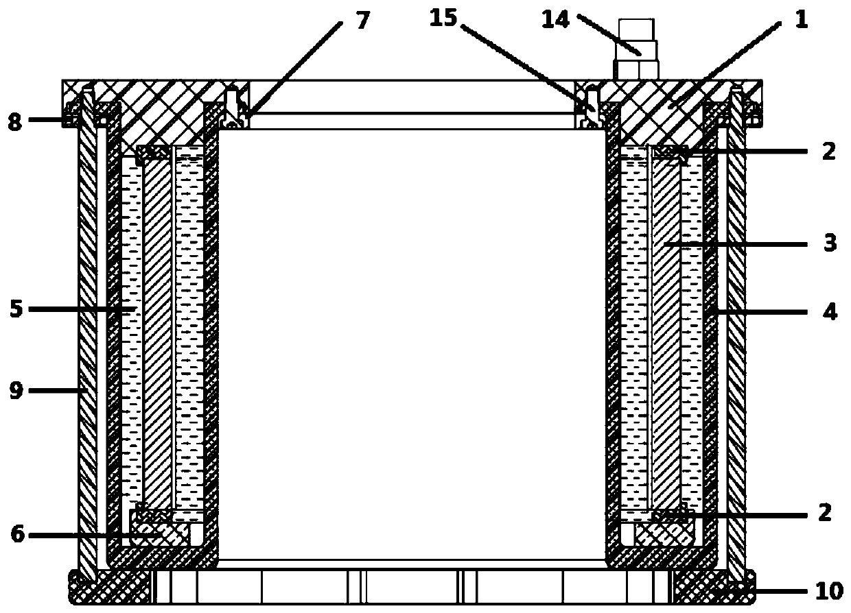
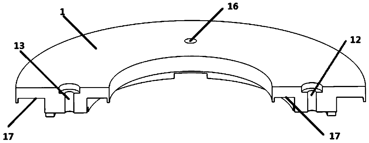
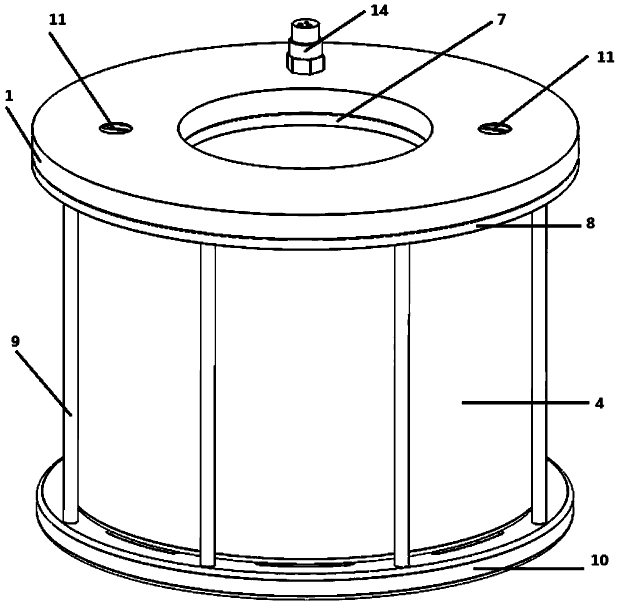
[0018] to combine Figure 1 to Figure 3 , the deep-sea broadband inlaid ring transducer of the present invention mainly includes a metal back plate 1, an upper and lower coupling positioning ring 2, an inlaid and assembled ceramic ring 3, a U-shaped rubber bag 4, oil 5 filled inside the rubber bag, and a positioning ring. Ring 6, inner snap ring 7, outer snap ring 8, support rod 9, base 10, sealing cap 11, watertight cable head 14, screw 15 and other structures. Oil injection holes 12, air outlet holes 13, electrical connection holes 16 and watertight grooves 17 are arranged on the metal back plate. The upper and lower ends of the ceramic ring are connected to the decoupling positioning ring and are connected to the metal back plate 1 and the positioning ring 6. Specifically, an upper decoupling positioning ring is arranged on the to...


PUM


Abstract

The invention provides a deep sea broadband inlaid ring energy converter. The deep sea broadband inlaid ring energy converter comprises a base, a metal backboard, supporting rods evenly arranged between the metal backboard and the base, an upper decoupling positioning ring connected with the lower end face of the metal backboard, an inlaid ceramic ring connected with the upper decoupling positioning ring, a lower decoupling positioning ring arranged at the lower end of the inlaid ceramic ring, a positioning ring connected with the lower end of the lower decoupling positioning ring and a U-shaped rubber capsule. The U-shaped rubber capsule is nested outside a ring structure formed by the upper decoupling positioning ring, the inlaid ceramic ring, the lower decoupling positioning ring and the positioning ring. The upper end of the U-shaped rubber capsule is connected with the metal backboard. An air outlet, an oil filler hole and an electric connection hole are further formed in the metal backboard, and a watertight cable head is arranged on the electric connection hole. The U-shaped rubber capsule is nested in the inlaid ceramic ring and connected with the metal backboard to form the overall structure, the U-shaped rubber capsule is filled with oil, an overflow structure form is realized, and therefore deep sea working can be achieved.

Description

technical field [0001] The present invention relates to an underwater acoustic transducer technology, in particular to a deep-sea broadband mosaic ring transducer, which can be applied to active detection sonar, deep-sea acoustic communication, deep-sea countermeasures, marine environment monitoring, and submarine geological and landform detection. and other fields. Background technique [0002] Sound waves are the only energy carrier known to man so far that can be transmitted over long distances in seawater. Whether it is military operations or ocean development, sound waves are used as the medium for carrying information. Underwater tracking, detection, identification, communication, etc. in the military field, offshore oil and gas resource exploration, marine surveying and mapping, polar scientific research, seabed geological and landform imaging, and sea area hydrological conditions research and measurement in the civilian field are all inseparable from relevant underw...

Claims


Application Information

Patent Timeline
Patent Type & Authority Patents(China)
IPC IPC(8): G10K9/122H04R1/44
CPCG10K9/122H04R1/44
Inventor 周天放蓝宇卢苇
Owner HARBIN ENG UNIV
Why Eureka
Try Eureka