Micro-displacement amplifier and nano-positioning device

A technology of amplifier and micro-displacement, which is applied in the direction of instruments and instrument parts, etc., and can solve problems such as poor precision, complex structure, and small stroke

Active Publication Date: 2017-05-31
GUANGDONG UNIV OF TECH
View PDF6 Cites 5 Cited by
  • Summary
  • Abstract
  • Description
  • Claims
  • Application Information

AI Technical Summary

Problems solved by technology

[0006] In view of this, the first object of the present invention is to provide a micro-displacement amplifier, the structural design of which can effectively solve the problems of existing nano-

Method used


Image

  • Micro-displacement amplifier and nano-positioning device

Examples


Embodiment Construction

[0023] The embodiment of the invention discloses a micro-displacement amplifier to solve the problems of small stroke, poor accuracy and complex structure of the existing nano-positioning device.

[0024] The following will clearly and completely describe the technical solutions in the embodiments of the present invention with reference to the accompanying drawings in the embodiments of the present invention. Obviously, the described embodiments are only some, not all, embodiments of the present invention. Based on the embodiments of the present invention, all other embodiments obtained by persons of ordinary skill in the art without making creative efforts belong to the protection scope of the present invention.

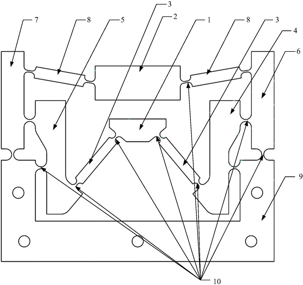
[0025] see figure 1 , figure 1 A schematic structural diagram of a micro-displacement amplifier provided by an embodiment of the present invention.

[0026] The micro-displacement amplifier provided by the embodiment of the present invention includes an input plat...


PUM


Abstract

The invention discloses a micro-displacement amplifier comprising an input platform and a fixed base. A pair of input connecting rods is symmetrically connected on the same side of the input platform. The other ends of the two input connecting rods are connected with the head ends of a first lever and a second lever correspondingly. The middle sections of the first lever and the second lever are connected with the two side positions of the fixed base correspondingly through flexible hinges. The tail ends of the first lever and the second lever are connected with the middle sections of a third lever and a fourth lever correspondingly through flexible hinges. The head ends of the third lever and the fourth lever are connected with the top ends of the two sides of the fixed base correspondingly through flexible hinges. The tail ends of the third lever and the fourth lever are connected with a pair of output connecting rods correspondingly through flexible hinges. The other ends of two output levers are symmetrically connected with the output platform. According to the micro-displacement amplifier, the problem that an existing nano-positioning device is small in travel, poor in precision and complex in structure is effectively solved. The invention further discloses a nano-positioning device.

Description

technical field [0001] The invention relates to the technical field of precision machining, more specifically, to a micro-displacement amplifier, and also to a nano-positioning device. Background technique [0002] At present, there are two mainstream methods to achieve large travel and high positioning accuracy of the motion platform: one is to use a macro-micro two-stage worktable, the macro-motion table achieves a large stroke, and the micro-motion table achieves the final positioning accuracy. The main idea of ​​this type of positioning platform design is to combine two types of motors, the DC motor controls the large-scale movement of the mechanism, and the piezoelectric ceramic actuator ensures the high precision of the end effector. This method overcomes the shortcoming of the traditional micro-manipulation robot with a small working space, but the overall drive system has a complex structure, large volume, high cost, and cannot be miniaturized. [0003] The other is...

Claims


Application Information

Patent Timeline
IPC IPC(8): G12B5/00
CPCG12B5/00
Inventor 何思丰汤晖邱迁车俊杰向晓彬陈创斌张凯富高健陈新贺云波王素娟
Owner GUANGDONG UNIV OF TECH
Why Eureka
Try Eureka