
Storage battery fixing mechanism, storage battery module assembly and automobile

A technology for fixing a mechanism and a battery, applied in the automotive field, can solve the problems affecting the service life of the battery 4, easy deformation and failure, and difficult to disassemble, etc., and achieves the effect of improving the efficiency of fixed installation, improving the thermal management performance, and facilitating the operation of personnel.

Inactive Publication Date: 2017-05-31
ANHUI JIANGHUAI AUTOMOBILE GRP CORP LTD
View PDF5 Cites 2 Cited by
  • Summary
  • Abstract
  • Description
  • Claims
  • Application Information

AI Technical Summary

Problems solved by technology

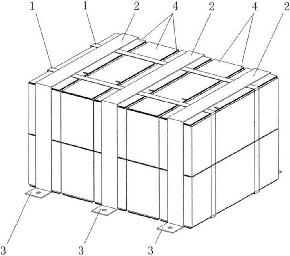
[0003] However, the fixed pressing plate 2 can only prevent the movement of the battery module in the front, rear and up and down directions, but cannot limit the movement of the battery module in the left and right directions, and the fixed pressing plate 2 is prone to deformation and failure after being used for a long time; in addition, the battery module There is no heat dissipation structure, so the heat of the battery 4 cannot be dissipated in time, which affects the service life of the battery 4; and the battery 4 is not easy to disassemble after being bound by the fixing belt 1. When the battery 4 fails, the battery module can only be replaced as a whole, which wastes costs

Method used


Image

  • Storage battery fixing mechanism, storage battery module assembly and automobile
  • Storage battery fixing mechanism, storage battery module assembly and automobile
  • Storage battery fixing mechanism, storage battery module assembly and automobile

Examples


Embodiment Construction

[0031] Embodiments of the present invention are described in detail below, examples of which are shown in the drawings, wherein the same or similar reference numerals designate the same or similar elements or elements having the same or similar functions throughout. The embodiments described below by referring to the figures are exemplary only for explaining the present invention and should not be construed as limiting the present invention.

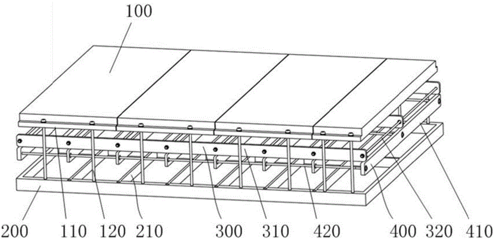
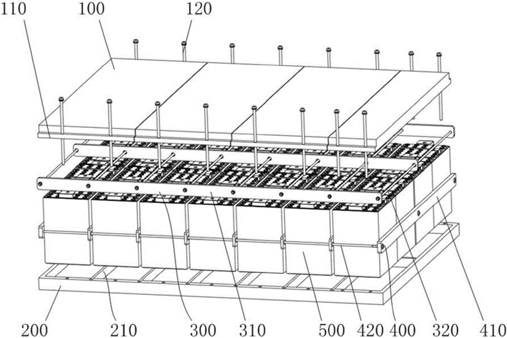
[0032] figure 2 A structural schematic diagram of the battery fixing mechanism provided by the present invention, image 3 It is an exploded view when the battery fixing mechanism provided by the present invention cooperates with the battery.

[0033] Please also refer to figure 2 and image 3 , the embodiment of the present invention provides a battery fixing mechanism, which includes: an upper cover plate 100, a lower cover plate 200, a first cooling frame 400 and a second cooling frame 300; Fixedly connected, the upper surface o...


PUM


Abstract

The invention discloses a storage battery fixing mechanism, a storage battery module assembly and an automobile. The storage battery fixing mechanism comprises an upper cover plate, a lower cover plate, a first cooling frame and a second cooling frame, wherein the upper cover plate is fixedly connected with the lower fixed cover plate through a bolt; the storage battery is fixedly arranged between the upper cover plate and the lower cover plate; the first cooling frame comprises a plurality of first partition plates which are uniformly distributed in parallel; the second cooling frame comprises a plurality of second partition plates which are uniformly distributed in parallel; and the arrangement directions of the first partition plate and the second partition plates are vertical to each other. According to the storage battery fixing mechanism, the storage battery module assembly and the automobile, storage batteries are fixed and pressed between the upper cover plate and the lower cover plate through the arrangement of the upper cover plate and the lower cover plate, so that fixing of the storage batteries in the vertical direction is achieved; the first cooling frame and the second cooling frame fixedly sleeve the storage batteries through the arrangement of the first cooling frame and the second cooling frame, so that fixing of the storage battery in the horizontal direction is achieved; and the radiating capability of the storage batteries is ensured through the first partition plates and the second partition plates.

Description

technical field [0001] The invention relates to the technical field of automobile batteries, in particular to a battery fixing mechanism, a battery module assembly and an automobile. Background technique [0002] Lithium-ion power battery is an important component of new energy vehicles and the power source of new energy vehicles. The lithium-ion power battery is usually fixedly arranged in the battery box on the car through the battery fixing mechanism. figure 1 It is a structural schematic diagram of the battery module fixing mechanism in the prior art, such as figure 1 As shown, the battery module fixing mechanism includes a fixing belt 1 and a fixing pressure plate 2, and the fixing pressure plate 2 is provided with a flanging 3; The flange 3 on the 2 will be fixed on the automobile with the battery module fixed by the fixing band 1. [0003] However, the fixed pressing plate 2 can only prevent the movement of the battery module in the front, rear and up and down dire...

Claims


Application Information

Patent Timeline
IPC IPC(8): H01M2/10H01M10/613H01M10/625H01M10/6555
CPCH01M2220/20H01M10/613H01M10/625H01M10/6555H01M50/20Y02E60/10
Inventor 叶昌森李文杰周从源汪文江许二超何俊刘雪冰吴鹏李杰李荫荣李高水徐赟张茂飞李坤鹏
Owner ANHUI JIANGHUAI AUTOMOBILE GRP CORP LTD
Learn More