

Electric power steering apparatus
An electric power steering and electric motor technology, which is applied in the direction of electric steering mechanism, power steering mechanism, steering mechanism, etc., can solve the problems of increasing the size of the motor, increasing the number of electronic components, increasing the installation area of the control circuit, etc., to ensure heat dissipation, The effect of increasing the installation area
- Summary
- Abstract
- Description
- Claims
- Application Information
AI Technical Summary
Problems solved by technology
Method used
Image

Examples
Embodiment approach 1
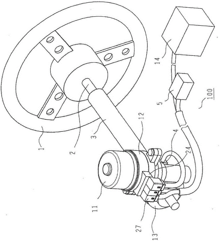
[0029] figure 1 It is a perspective view showing the electric power steering device according to Embodiment 1 of the present invention, and shows the configuration of a general column-type electric power steering device. exist figure 1 Among them, the electric power steering device 100 includes: a steering wheel 1, which steers the vehicle; a steering shaft 2, which is connected to the steering wheel 1; a steering column 3, in which the steering shaft 2 is installed become able to rotate freely; torque sensor 4, the torque sensor 4 detects the steering torque of the steering wheel 1; vehicle speed sensor 5, the vehicle speed sensor 5 detects the running speed of the vehicle; Apply steering assist force; the control device 12, the control device 12 inputs the signals of the torque sensor 4 and the vehicle speed sensor 5, and controls the driving of the above-mentioned electric motor 11 correspondingly to the steering torque and the driving conditions of the vehicle; the transm...
Embodiment approach 2
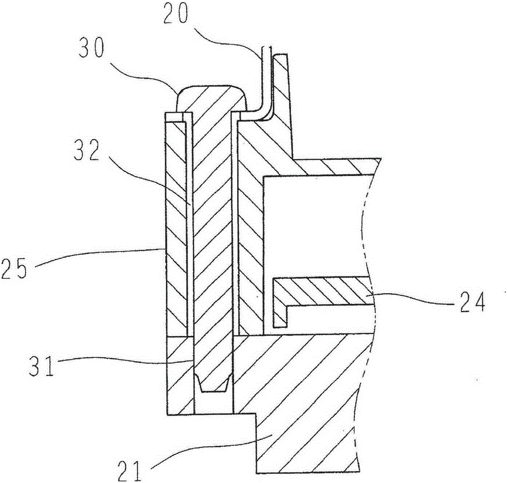
[0040] image 3 It is an enlarged partial cross-sectional view of a screw portion of the electric power steering system according to Embodiment 2 of the present invention, and is a diagram showing the configuration of the electric motor 11 and the control device 12 . exist image 3 Among them, the three parts of the motor frame 20 , the casing 25 and the plate 21 are fixed by screws 30 . In addition, at least one of the plate 21 and the case 25 is formed of magnesium or a magnesium alloy, and at least one portion formed of the magnesium or magnesium alloy is provided with a through hole 32 for the screw 30 . A female screw part 31 is formed on a part made of a metal material other than magnesium or magnesium alloy, and the screw 30 is inserted into the through hole 32 and screwed to the female screw part 31, and clamped by applying an axial force of the screw Fixed binding. Other structures are the same as those in Embodiment 1.
[0041] According to this structure, when t...
Embodiment approach 3
[0043] Figure 4a It is an enlarged partial cross-sectional view showing a screw portion of the electric power steering device according to Embodiment 3 of the present invention. In Embodiment 2 described above, the female screw portion 31 is formed at a portion formed of a metal material other than magnesium or a magnesium alloy, but in Figure 4a In the illustrated third embodiment, the female thread portion 31 is formed on the burring portion 33 formed by burring the motor frame 20 (Japanese: burring processing). Other structures are the same as those in Embodiment 2. According to such a structure, the same effect as Embodiment 2 can be acquired.
PUM
 Abstract
Description
Claims
Application Information