Press-connection mechanism

A pivotal connection and pivotal point technology, applied in the field of wire harness processing equipment, can solve the problems of terminal deviation, large clamping force, terminal clamping damage, etc., and achieve the effect of convenient use, simple structure and appropriate clamping force

Active Publication Date: 2017-05-31
XIAMEN HIPRECISE TECH CO LTD
View PDF8 Cites 4 Cited by
  • Summary
  • Abstract
  • Description
  • Claims
  • Application Information

AI Technical Summary

Problems solved by technology

[0003] In the process of processing the wire harness, the terminal can be crimped on the wire harness with the above-mentioned crimping pliers. This kind of crimping pliers is simple in structure, practical and convenient, but when performing the crimping work, it is necessary to rely on manual operation to complete the crimping terminal of the wire harness.
However, in the existing wire harness processing, automatic equipment is often used to automatically process the wire harness. When the crimping pliers are used in the automatic wire harness processing equipment, there will be the following defects: the crimping pliers cannot pre-clamp the terminals, so that the wire harness after crimping Terminal deviation; in addition, when applying external force to the crimping pliers for crimping, it is impossible to guarantee whether the clamping force of the clamping terminal is reasonable. Large, easy to cause the terminal to be clamped and damaged, not suitable for automatic equipment for wire harness processing

Method used


Image

  • Press-connection mechanism
  • Press-connection mechanism
  • Press-connection mechanism

Examples


Embodiment Construction

[0014] Below in conjunction with accompanying drawing and specific embodiment, the present invention will be further described:

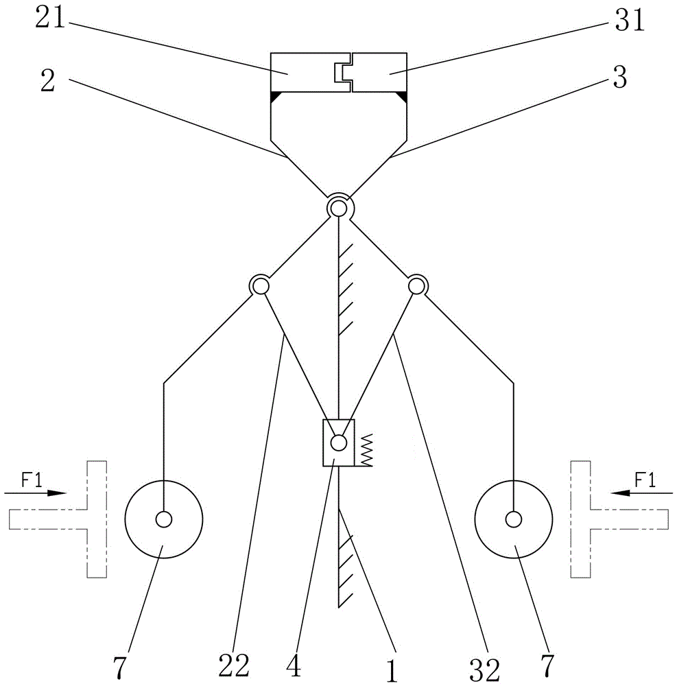
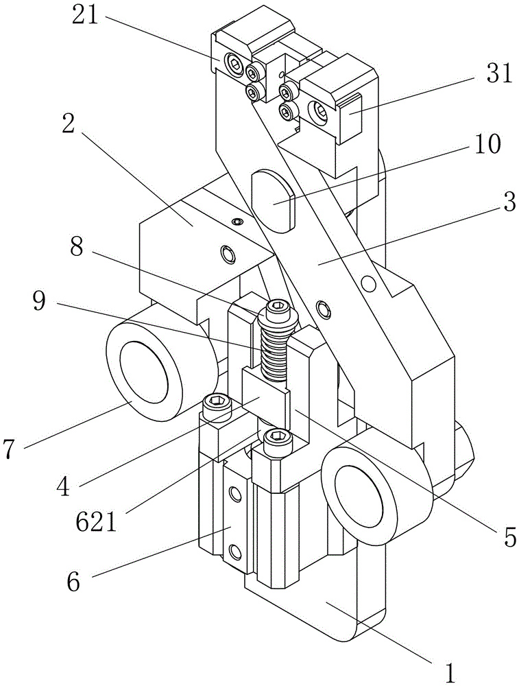
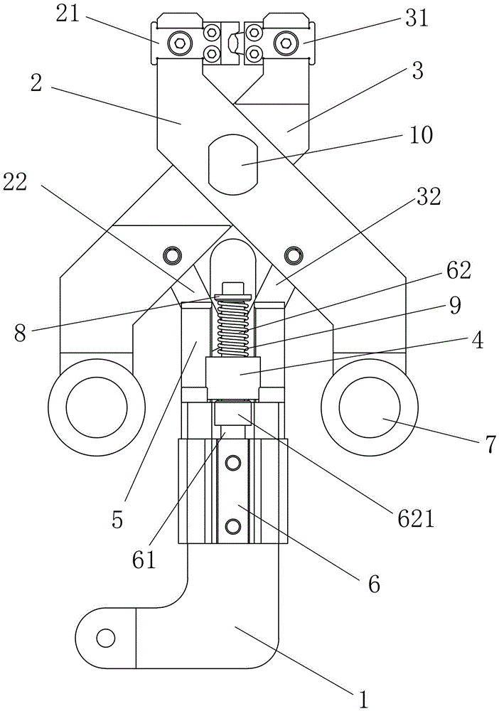
[0015] see figure 1 , figure 2 and image 3 , the present invention relates to a crimping mechanism, and its preferred embodiment includes a frame 1, on which a first crimping arm 2 and a second crimping arm 3 pivotally connected in the middle are arranged, the first crimping arm The middle parts of the arm 2 and the second crimping arm 3 are pivotally connected to each other through a pivot 10, and the pivot 10 is pivotally connected with the lock block (not shown) on the frame 1; the upper end of the first crimping arm 2 is bolted The die 21 is fixed, the upper end of the second crimping arm 3 is fixed with a punch 31 with bolts, the first crimping arm 2 is pivotally connected with the first connecting rod 22 between the end and the middle hinge point, and the second crimping arm 3 A second connecting rod 32 is pivotally connected between the ...


PUM


Abstract

The invention discloses a press-connection mechanism. The press-connection mechanism includes a first press-connection arm and a second press-connection arm, the middle portions of the first press-connection arm and the second press-connection arm are connected with each other through a pivot in a pin-jointed mode, the upper end of the first press-connection arm is provided with a first vice jaw, and the upper end of the second press-connection arm is provided with a second vice jaw. The mechanism is characterized in that the position located between the tail end and a middle pin-jointed point of the first press-connection arm is connected with a first connection rod in a pin-jointed mode, the position located between the tail end and a middle pin-jointed point of the second press-connection arm is connected with a second connection rod in a pin-jointed mode, and one tail end of the first connection rod and one tail end of the second connection rod are connected with one sliding block in a pin-jointed mode; the sliding block is connected with a sliding groove in a sliding mode, a power device is fixed on the sliding groove and used for driving the sliding block to slide on the sliding groove, and the lower end of the first press-connection arm and the lower end of the second press-connection arm are externally connected with press-connection power. According to the press-connection mechanism, a wiring harness can automatically be in press connection with a terminal, no manual operation is needed, the structure is simple, and the press-connection mechanism is convenient to use and can be used in automatic equipment.

Description

technical field [0001] The invention relates to a wire harness processing equipment, in particular to a crimping mechanism for crimping a terminal and a wire harness into one body. Background technique [0002] The general structure of the crimping pliers includes a first pliers arm and a second pliers arm hinged together in the middle, and the upper ends of the first pliers arm and the second pliers arm are respectively provided with a first jaw and a second jaw, and the first jaw and the second jaw constitute a crimping portion, and the lower ends of the first tong arm and the second tong arm are respectively hinged with a first handle and a second handle. [0003] In the process of processing the wire harness, the terminal can be crimped on the wire harness with the above-mentioned crimping pliers. This kind of crimping pliers has a simple structure, is practical and convenient, but when performing the crimping work, it is necessary to rely on manual operation to complete...

Claims


Application Information

Patent Timeline
Patent Type & Authority Applications(China)
IPC IPC(8): H01R43/048
CPCH01R43/048
Inventor 李普天蔡龙清陈明峰陈启耀
Owner XIAMEN HIPRECISE TECH CO LTD
Why Eureka
Try Eureka