
Electricity drawer device

A drawer cabinet and equipment technology, applied in pull-out switch cabinets, electrical components, switchgear, etc., can solve problems such as potential safety hazards, increased risk of electric shock for maintenance personnel, and inconvenient maintenance of electrical components, so as to facilitate maintenance and repair, avoid Risk of electric shock, effect of improving flexibility

Active Publication Date: 2017-05-31
温州正合知识产权服务有限公司
View PDF5 Cites 7 Cited by
  • Summary
  • Abstract
  • Description
  • Claims
  • Application Information

AI Technical Summary

Problems solved by technology

[0002] The power drawer is an important part of power equipment, mainly used to install electrical components to ensure the normal operation of the electrical components. In order to facilitate the installation of electrical components, the power drawer is usually set in a pull-out manner. The electrical connection mode of the electrical components in the drawer cabinet is basically always powered by plugging. Due to the particularity of the plug-in power supply mode, no matter whether the drawer cabinet is in the pulled out state or the inserted state, the electrical components in the drawer cabinet are always in the state. It is very inconvenient for the maintenance of electrical components. When the drawer cabinet is pulled out for maintenance, the electrical components in it cannot be powered off by themselves, which increases the risk of electric shock for maintenance personnel and poses a greater safety hazard. Hidden danger

Method used


Image

  • Electricity drawer device
  • Electricity drawer device
  • Electricity drawer device

Examples


Embodiment Construction

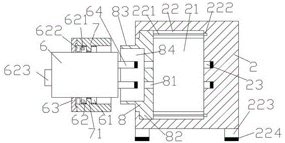
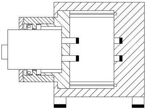
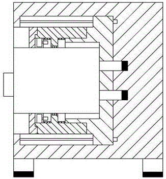
[0019] Such as Figure 1-Figure 4 As shown, a kind of electric drawer equipment of the present invention, comprises cabinet base 2 and the drawer cabinet 6 that is arranged on the left side of described cabinet base 2, described cabinet base 2 is provided with pushing chamber 21, and described pushing chamber 21 is up and down The two sides are oppositely provided with a sliding cavity 22, the sliding cavity 22 is provided with a screw rod 221, the right end of the screw rod 221 is connected with the first motor 222, and the pushing cavity 21 is provided with a sliding block 8. The upper and lower sides of the sliding block 8 are oppositely provided with stoppers 82 protruding into the sliding chamber 22. The stoppers 82 are threadedly connected with the screw rod 221, and the sliding The left side of the block 8 is provided with an external thread connecting portion 83, the external thread connecting portion 83 is provided with a push groove 84, and the sliding block 8 on the...


PUM


Abstract

The invention discloses an electricity drawer device, which comprises a cabinet base and a drawer which is arranged on the left side of the cabinet base, pushing cavity is arranged in the cabinet base, the upper and lower side of the pushing cavity are relatively provided with a slip cavity, the slip cavity is provided with a screw, the right side of the screw is connected with a first motor, slide block is arranged in the pushing cavity, the upper and lower side of the slide block are provided relatively with stop dog which extrudes in the slide cavity, the dog stop is connected with screw and screw whorl coordinately, the left side of the slide block is provided with outer screw whorl connection part, pushing slot is arranged in the outer screw whorl connection part, a cross-under hole is arranged in the right side of the pushing slot, the side wall of the cabinet case opposite to the right side of the cross-under hole is provided with an, the pushing slot and the drawer is arranged relatively; the structure is simple, operation is convenient, safety is high, power supplying is stable, the electric shock hazard caused by the maintenance personnel touching the insert hole is avoided.

Description

technical field [0001] The invention relates to the technical field of electric equipment, in particular to an electric drawer equipment. Background technique [0002] The power drawer is an important part of power equipment, mainly used to install electrical components to ensure the normal operation of the electrical components. In order to facilitate the installation of electrical components, the power drawer is usually set in a pull-out manner. The electrical connection mode of the electrical components in the drawer cabinet is basically always powered by plugging. Due to the particularity of the plug-in power supply mode, no matter whether the drawer cabinet is in the pulled out state or the inserted state, the electrical components in the drawer cabinet are always in the state. It is very inconvenient for the maintenance of electrical components. When the drawer cabinet is pulled out for maintenance, the electrical components in it cannot be powered off by themselves, w...

Claims


Application Information

Patent Timeline
Patent Type & Authority Applications(China)
IPC IPC(8): H02B11/127
CPCH02B11/127
Inventor 陈玉飞
Owner 温州正合知识产权服务有限公司
Learn More