Data diversity combination method and system in repeated encoding system
A technology of repetitive coding and data, applied in the field of data diversity combining methods and systems, can solve the problems of inaccurate weights of MRC combining, reducing the quality of received signals, and channel attenuation of diversity data blocks, so as to improve the signal demodulation capability, improve the Channel fading and noise interference, the effect of increasing the suppression effect
- Summary
- Abstract
- Description
- Claims
- Application Information
AI Technical Summary
Problems solved by technology
Method used
Image

Examples
Embodiment 1
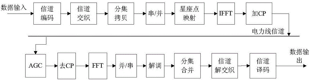
[0069] In the PLC system, two frequency bands are supported, namely frequency band 0 and frequency band 1 . Frequency band 0 has a total of 512 subcarriers, numbered from 0 to 511, and the maximum number of available subcarriers supported is 411, numbered from 80 to 490, all of which are used without shielding one or several subcarriers in the middle; supported by frequency band 1 There are 131 sub-carriers, numbered from 100 to 230, all of which are used, and one or several sub-carriers in the middle are not shielded. like Figure 6 Shown is a physical layer link processing process of a PLC system. In this system, the processing is divided into two parts: frame control and load data. Among them, the frame control part adopts a fixed diversity copy mode according to the used frequency band (0 or 1) when transmitting data each time, while the diversity copy mode of the load data part can be changed according to the current channel quality. Diversity copy parameters will be gi...
Embodiment 2
[0106] Next, take the physical layer diversity copy process of the payload data part of frequency band 1 and TMI=1 as an example. The specific steps are as follows, and the process is as follows: Figure 7 shown.
[0107] Step 1: The system sets the communication frequency band to be frequency band 1, and the transmitting end sets the diversity copy mode of the payload part to TMI=1, and puts the TMI value into the frame control part. The frame control part adopts QPSK modulation, 12 OFDM symbols.
[0108] Step 2: The payload data is processed by scrambling, Turbo coding, and channel interleaving according to this, and then input to the diversity copy module. According to TMI = 1, support PB520, the number is 1 to 4 physical blocks, and the physical block is used as the unit for processing in each module. 520Byte×8=4160bit, after Turbo coding with a code rate of 1 / 2, the number of bits of a single physical block entering the diversity copy is DataBitsLen=4160bit×2=8320bit. ...
PUM
 Abstract
Description
Claims
Application Information