Transmission method and device for channel sounding signal

A technology of channel detection signal and transmission method, applied in the field of channel detection signal transmission method and device, can solve problems such as small transmission range, and achieve the effects of improving power spectral density and transmission range

Active Publication Date: 2019-06-07
BEIJING SPREADTRUM HI TECH COMM TECH CO LTD
View PDF3 Cites 0 Cited by
  • Summary
  • Abstract
  • Description
  • Claims
  • Application Information

AI Technical Summary

Problems solved by technology

[0003] In large bandwidth scenarios, the transmission range of existing channel sounding signal transmission methods is small

Method used


Image

  • Transmission method and device for channel sounding signal
  • Transmission method and device for channel sounding signal
  • Transmission method and device for channel sounding signal

Examples


Embodiment Construction

[0038] As mentioned above, in a large bandwidth scenario, the transmission range of the existing channel sounding signal transmission method is relatively small.

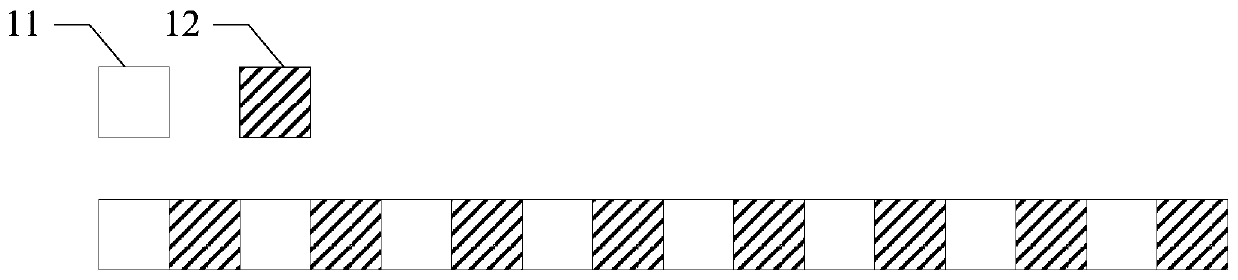
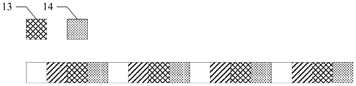
[0039] Existing LTE generally uses the following methods for SRS transmission, one of which is to occupy one symbol and use a continuous long sequence in the frequency domain for transmission; the other is to occupy multiple symbols and use a continuous short sequence in the frequency domain for transmission. The above two transmission methods usually implement frequency domain mapping in the form of comb teeth. For details, please refer to Figure 1a and Figure 1b , where legends 11, 12, 13, and 14 represent different comb teeth.

[0040] Figure 1a Indicates the case where the comb teeth are 2, that is, frequency mapping is performed at intervals of 1 subcarrier; Figure 1b The case where the number of comb teeth is 4 is indicated, that is, the frequency domain mapping is performed at intervals of 3 subcarriers....


PUM


Abstract

The present invention provides a transmission method and device for a channel sounding signal. The method includes: receiving configuration information issued by the network side, the configuration information includes a first frequency domain pattern at the resource block level, and the first frequency domain pattern indicates a system A resource block used for transmitting a channel sounding signal within the bandwidth; sending a channel sounding signal by using the resource block indicated by the first frequency domain pattern. The method and device can improve the transmission range of the channel detection signal.

Description

technical field [0001] The present invention relates to the field of communications, in particular to a method and device for transmitting a channel detection signal. Background technique [0002] The channel sounding signal (SRS, Sounding Reference Signal) is an uplink reference signal. The network side can use the channel sounding signal to detect the quality of the uplink channel. It can usually be used to provide reference for eNodeB scheduling and uplink and downlink channel reciprocity. [0003] In a large bandwidth scenario, the transmission range of the existing channel sounding signal transmission method is relatively small. Contents of the invention [0004] The technical problem solved by the invention is to improve the transmission range of the channel detection signal transmission method. [0005] In order to solve the above technical problems, an embodiment of the present invention provides a channel sounding signal transmission method, including: receiving ...

Claims


Application Information

Patent Timeline
Patent Type & Authority Patents(China)
IPC IPC(8): H04W24/08H04W72/04H04W72/08H04W72/12
CPCH04W24/08H04W72/0453H04W72/542H04W72/20
Inventor 王化磊
Owner BEIJING SPREADTRUM HI TECH COMM TECH CO LTD
Why Eureka
Try Eureka