Devices for Line of Sight Detection

A line-of-sight detection and line-of-sight technology, applied to color TV parts, TV system parts, TVs, etc., can solve problems such as inability to receive light, and achieve image display, miniaturization, and correct image display effects

Active Publication Date: 2020-03-27
FOVE INC
View PDF15 Cites 0 Cited by
  • Summary
  • Abstract
  • Description
  • Claims
  • Application Information

AI Technical Summary

Problems solved by technology

Therefore, the line-of-sight input device facing the LCD will be blocked by the half mirror and cannot receive light from the LCD.

Method used


Image

  • Devices for Line of Sight Detection
  • Devices for Line of Sight Detection
  • Devices for Line of Sight Detection

Examples


no. 1 example

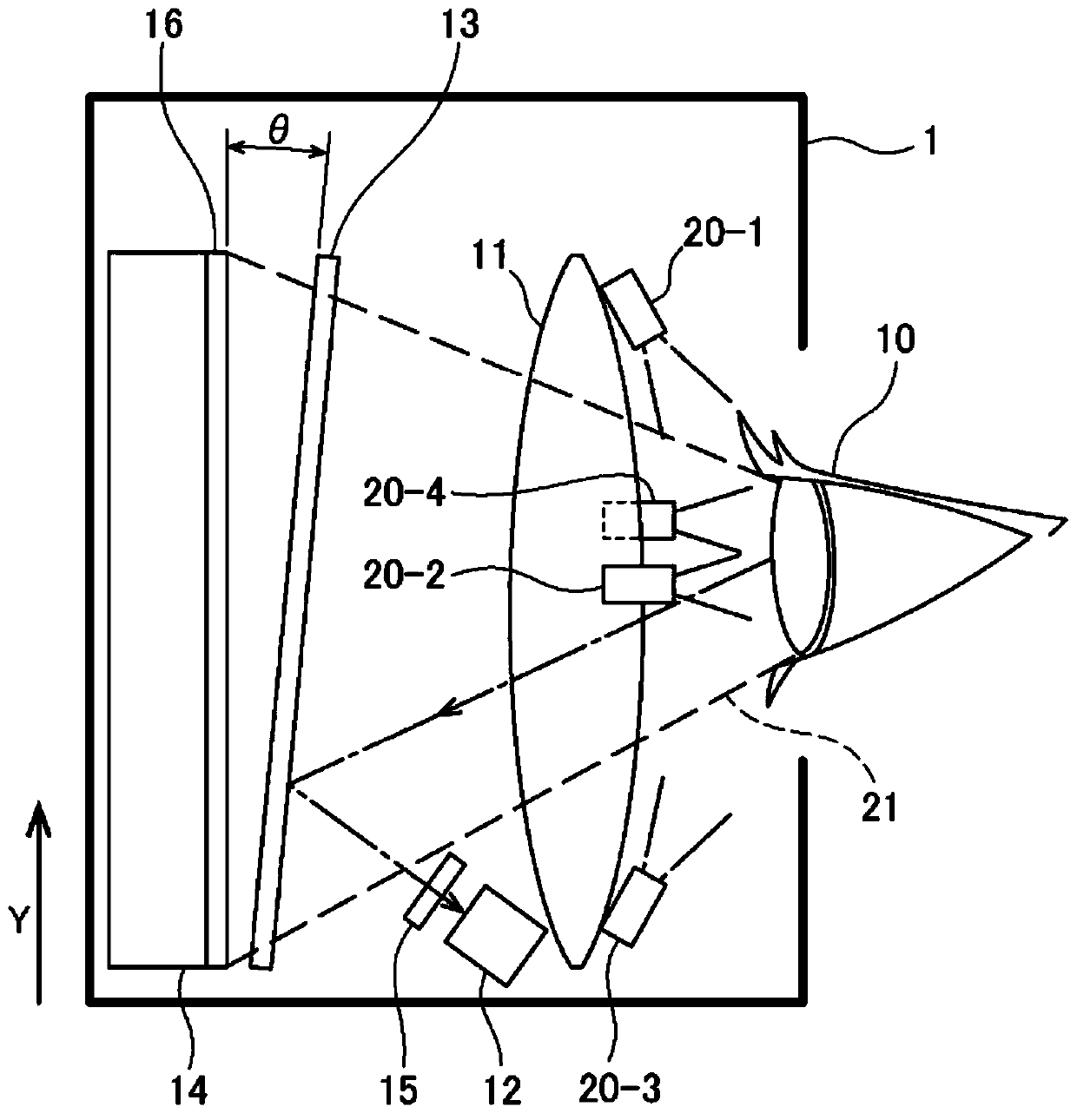
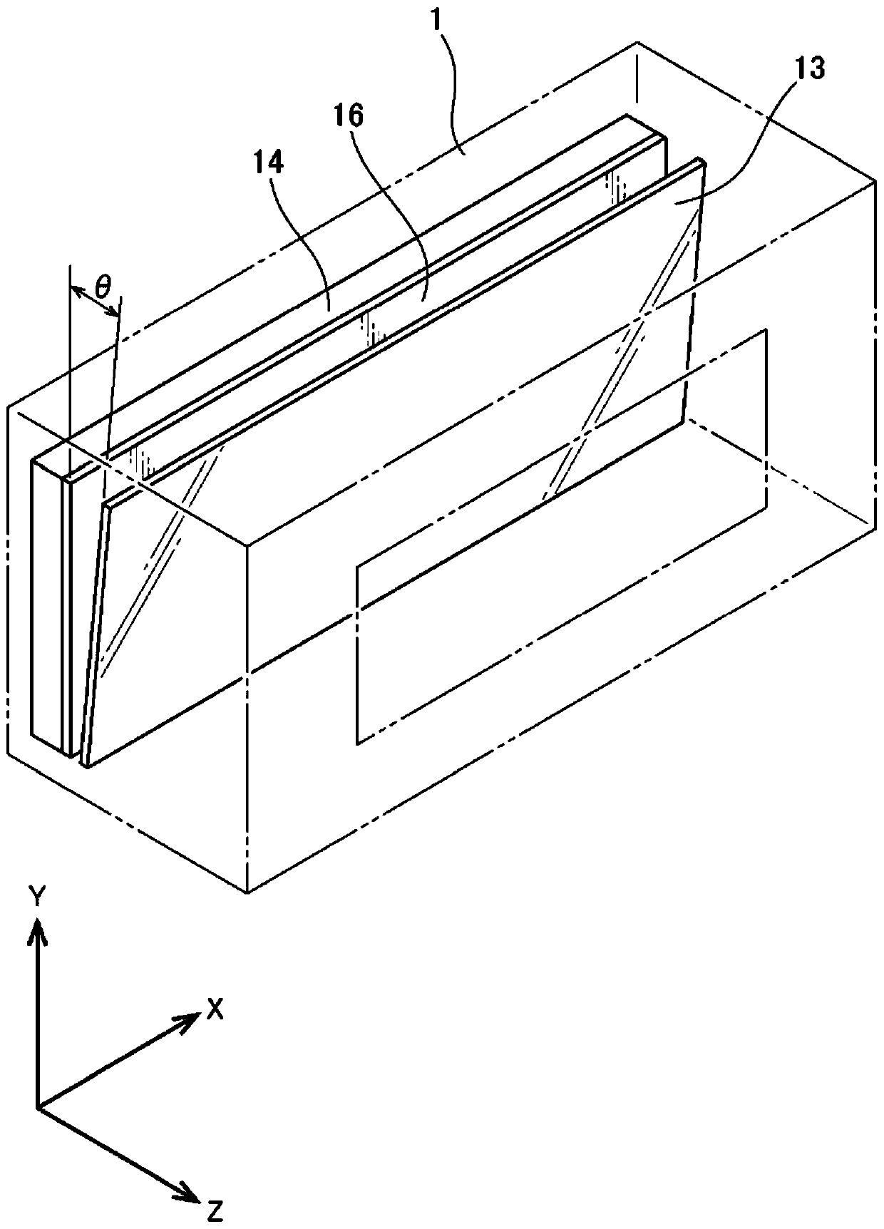
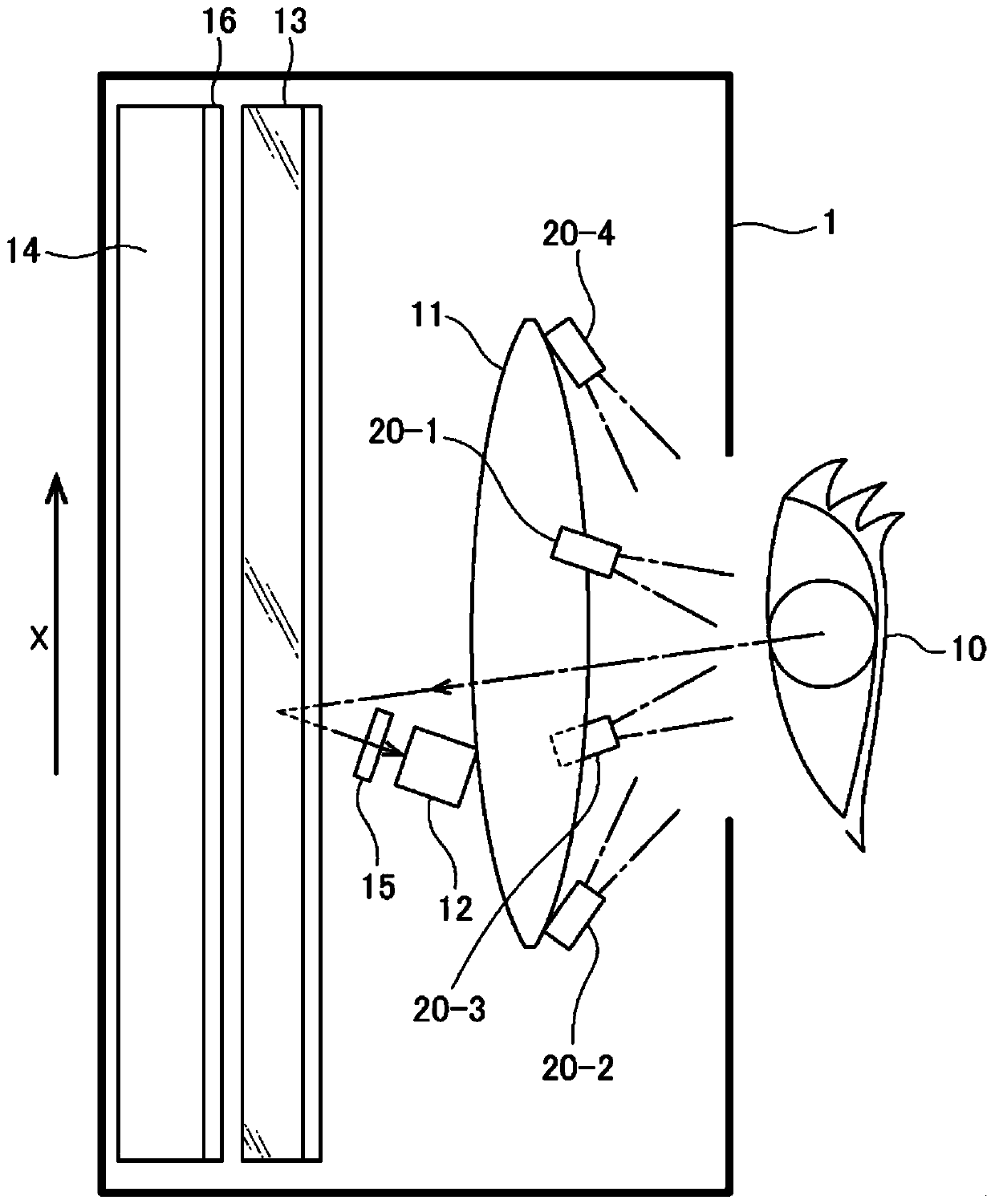
[0049] figure 1 A schematic side view of the head-mounted display HMD in the first embodiment of the present invention is shown. The head-mounted display 1 mounted on the user's head includes a display 14 , and the display 14 has a display surface 16 . The device for line-of-sight detection installed in the head-mounted display also includes: an invisible light emitting device 20 that emits invisible light to the user's eyes 10, an invisible light reflector 13 that reflects the invisible light and allows visible light to pass through, and a photographing device 12. Capable of taking pictures of images formed by invisible light, and a filter 15 to allow invisible light to pass through and visible light not to pass through. Furthermore, the device for line-of-sight detection has a lens 11 at a position between the display 14 and the user's eyes 10 .

[0050] In this embodiment, although the infrared emitting devices 20-1-20-4 are used as the invisible light emitting devices 2...

no. 2 example

[0061] Figure 4 A schematic diagram showing the configuration of the head-mounted display of the second embodiment seen from above is drawn. In the following description, regarding the same structural components as those of the first embodiment, related descriptions will be appropriately omitted.

[0062] In this embodiment, the same configuration as that described in the first embodiment is provided for each of the two eyes of the user. That is, with respect to the user's right eye 10a, the head-mounted display 1 is equipped with a display 14a, between the display 14a and the right eye 10a, and between the display 14a and the imaging device 12a, a thermal mirror 13a, The lens 11a installed between the display 14a and the user's right eye 10a, the infrared emitting device 20a-1-20a-4 that emits infrared rays to the user's right eye 10a, and at least A photographic device 12a installed in a local direction, and an anti-visible light filter 15a installed between the photograp...

no. 3 example

[0068] Figure 5 A schematic diagram showing the configuration of the head-mounted display of this embodiment seen from above is drawn. The following description will focus on the differences from the second embodiment. In order to simplify the description, only the two structures of the front displays 14 a and 14 b will be described as displays. Furthermore, it is also possible to add a display on the side and the bottom. Furthermore, the displays 14a and 14b may be integrally formed as a single display.

[0069] In this embodiment, the photographing device 12 is a single photographing device shared by the left and right eyes. Orient the single photographing device in such a direction that the photographing range covers at least a part of the display surface of at least one of the displays 14a and 14b. Furthermore, two heat mirrors 13a and 13b are prepared, and each heat mirror is attached between each eye of the user and each of the two displays 14a and 14b. Figure 5 T...


PUM


Abstract

An object of the present invention is to reduce the size of a device for line-of-sight detection. A device for line-of-sight detection in a head-mounted display, including an invisible light emitting device that emits invisible light to the user's eyes, an invisible light reflector that reflects the invisible light and allows visible light to pass through, and a filter, Allowing invisible light to pass through but not visible light to pass through, and a photographing device capable of photographing an image formed by invisible light, wherein a different The visible light reflector is installed so that the angle between the surface of the invisible light reflector and the display surface of the display is more than 0 degrees and less than 45 degrees, and is used to reflect the invisible light emitted from the invisible light emitting device to the user's eyes reflect the reflected invisible light, install a filter at the position between the display and the photographing device, install the photographing device in a direction that enables the photographing range of the photographing device to cover at least a part of the display surface of the display, and The image of the user's eyes formed by the invisible light reflected by the invisible light reflector is photographed.

Description

technical field [0001] The present invention relates to a device for line of sight detection, and in particular to a device for line of sight detection used in a head-mounted display (HMD). Background technique [0002] like Figure 8 As shown, the conventional line-of-sight detection device that takes pictures of the user's eyes to estimate the line-of-sight of the user has a lens 61, an infrared emitting device 62, a heat mirror 63 that reflects infrared rays and allows visible light to pass through, a camera 64, and a display 65. The angle of the thermal mirror 63 is about 45 degrees with respect to the optical axis 66 extending vertically from the display surface of the display 65, and the angle θ is inclined at 45 degrees with respect to the display surface of the display. The camera 64 is mounted below the optical axis 66 , facing the optical axis in a direction perpendicular to the optical axis 66 . The infrared rays emitted from the infrared emitting device 62 are r...

Claims


Application Information

Patent Timeline
Patent Type & Authority Patents(China)
IPC IPC(8): H04N5/225
CPCG02B2027/0138G02B2027/0187G02B27/0093G02B27/0172H04N5/33G06V40/19G02B27/02H04N23/57G02B27/149H04N23/90G06F3/013
Inventor 洛克拉因·威尔逊赵漠居
Owner FOVE INC
Why Eureka
Try Eureka