Media-Tight Housing

A shell and seal technology, applied in the field of medium-sealed shells, can solve problems such as high-frequency interference

Active Publication Date: 2017-05-31
ZF FRIEDRICHSHAFEN AG
View PDF6 Cites 3 Cited by
  • Summary
  • Abstract
  • Description
  • Claims
  • Application Information

AI Technical Summary

Problems solved by technology

It has proven to be a disadvantage here that due to the non-negligible feed line of the power supply unit to the circuit board, high-frequency interference can occur in the supply line to the circuit board

Method used


Image

  • Media-Tight Housing

Examples


Embodiment Construction

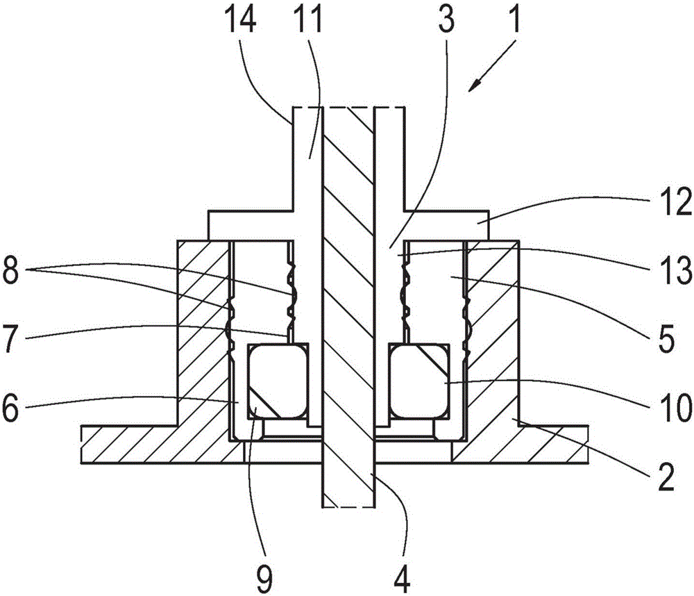
[0015] The installation 1 has a housing 2 with an opening 3 . The busbar 4 is guided through the opening 3 . The bus bars 4 connect an external power supply (not shown) to a circuit board (not shown), the circuit board being positioned in the interior of the housing 2 .

[0016] The form seal 5 can be seen in the opening 3 of the housing 2 . The form seal 5 is substantially annular and has a radial cutout 9 in the region of the inner radius 7 , into which a ferrite core 10 can be inserted. The ferrite core 10 is designed as a one-piece or multi-piece ring core. Obviously, the ferrite core 10 can also be configured as a C-core or as a U-core.

[0017] However, it is also conceivable for the ferrite core 10 to be integrated into the form seal 5 , ie the form seal 5 completely surrounds the ferrite core 10 . The form seal 5 has a circumferential sealing lip 8 in the region of the outer radius 6 and / or in the region of the inner radius 7 . These sealing lips 8 serve on the on...


PUM


Abstract

The present invention relates to an arrangement comprising a housing (2) and at least one busbar (4) for connecting a printed circuit board, which is arranged in the housing (2), to a power supply which is present outside the housing (2), wherein the housing (2) has an aperture (3) out of which the busbar (4) projects, wherein a ferrite core (10) and a moulded seal (5), which accommodates the ferrite core (10), are inserted into the housing aperture (3) in a media-tight manner, and the moulded seal (5) containing the ferrite core (10) surrounds the busbar (4) in a form-fitting manner.

Description

technical field [0001] The invention relates to a device comprising a housing and at least one busbar for connecting a circuit board arranged in the housing to a power supply present outside the housing, wherein the housing has a feedthrough, The busbar protrudes from the feedthrough. Background technique [0002] Circuit boards are used in drive systems for motor vehicles with internal combustion electric drives to control and regulate electric machines. These circuit boards are usually positioned spatially close to the electric motor in the associated control unit. This positioning depends on the corresponding power supply of the power supply device. It has proven to be disadvantageous here that high-frequency disturbances may occur in the supply line to the circuit board due to the non-negligible supply line of the power supply unit to the circuit board. In addition, however, it must also be ensured that the printed circuit board is closed in a medium-tight manner, so ...

Claims


Application Information

Patent Timeline
Patent Type & Authority Applications(China)
IPC IPC(8): H05K5/00H05K5/06H05K9/00
CPCH01F2017/065H05K5/0069H05K5/069H05K9/0018H05K9/0098B60R16/03H02B1/20H05K5/0026
Inventor 汉斯-于尔根·汉夫特赫尔曼·图尔恩
Owner ZF FRIEDRICHSHAFEN AG
Why Eureka
Try Eureka