A hot gas defrosting method, hot gas defrosting and refrigeration cycle method

A hot gas, high temperature gas technology, applied in hot gas defrosting and refrigeration cycle, hot gas defrosting field, can solve the problems of liquid explosion, high energy consumption, poor defrosting effect, etc., to ensure the safety and reliability of use, improve the defrosting effect. effect of effect

Active Publication Date: 2019-09-13
广州市粤联水产制冷工程有限公司
View PDF6 Cites 0 Cited by
  • Summary
  • Abstract
  • Description
  • Claims
  • Application Information

AI Technical Summary

Problems solved by technology

[0006] The embodiment of the present invention discloses a hot gas defrosting method to solve the problem of poor defrosting effect of the current hot gas defrosting method and the liquid explosion easily caused by directly discharging the liquid in the evaporator into the low-pressure return air pipe and the low-pressure circulation barrel and greater energy consumption

Method used


Image

  • A hot gas defrosting method, hot gas defrosting and refrigeration cycle method
  • A hot gas defrosting method, hot gas defrosting and refrigeration cycle method
  • A hot gas defrosting method, hot gas defrosting and refrigeration cycle method

Examples


Embodiment 1

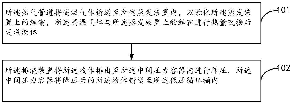
[0053] see figure 1 , is a flow chart of the hot gas defrosting method provided in Embodiment 1 of the present invention. in, figure 1 The described hot gas defrosting method can be applied to a hot gas defrosting system, and the hot gas defrosting system may include a hot gas pipeline, an evaporating device, a liquid draining device, an intermediate pressure vessel and a low-pressure circulation bucket connected in sequence. Such as figure 1 As shown, the hot gas defrosting method may include the following operations:

[0054] 101. The hot gas pipeline transports the high-temperature gas to the evaporator to melt the frost on the evaporator. The above-mentioned high-temperature gas exchanges heat with the frost on the evaporator and becomes liquid.

[0055] In the embodiment of the present invention, the hot gas pipeline is also provided with a hot gas solenoid valve, the hot gas solenoid valve is electrically connected to an external control device, the startup time of th...

Embodiment 2

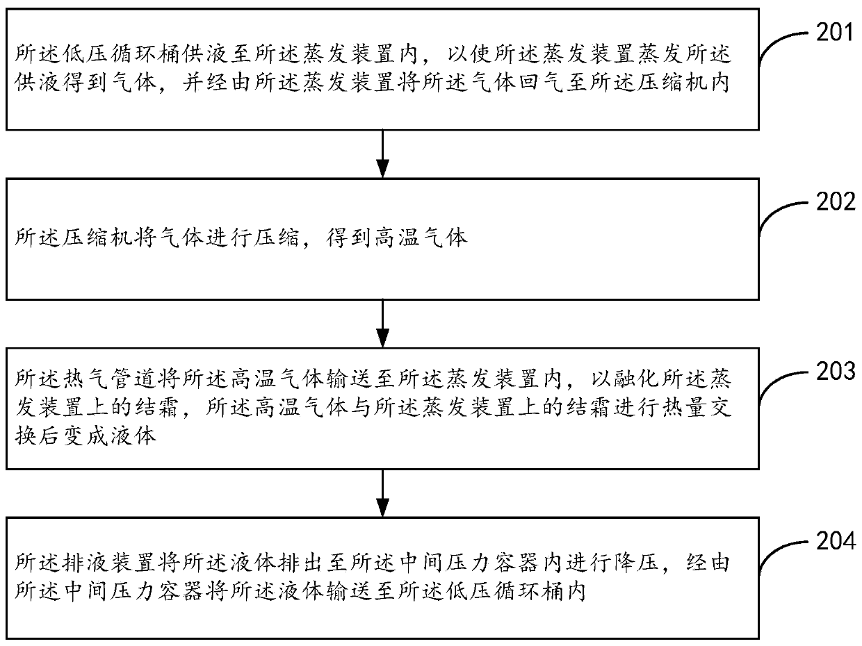
[0067] See figure 2 , is a flowchart of a hot gas defrosting and refrigeration cycle method disclosed in Embodiment 2 of the present invention. in, figure 2 The described hot gas defrosting and refrigeration cycle method can be applied in a hot gas defrosting and refrigeration cycle system, and the hot gas defrosting and refrigeration cycle system may include a hot gas pipeline, an evaporating device, a liquid discharge device, an intermediate pressure vessel, a low-pressure circulation barrel and compressor. Such as figure 1 As shown, the hot gas defrosting and refrigeration cycle method may include the following operations:

[0068] 201. The low-pressure circulation barrel supplies liquid to the evaporating device, so that the evaporating device evaporates the above-mentioned supplied liquid to obtain gas, and returns the gas to the compressor through the evaporating device.

[0069] 202. The compressor compresses the gas to obtain high-temperature gas.

[0070] 203. ...

Embodiment 3

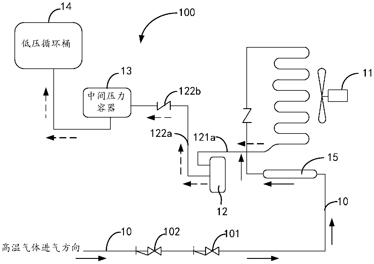
[0082] see image 3 , is a schematic structural diagram of the hot gas defrosting system 100 provided in Embodiment 3 of the present invention. A hot gas defrosting system 100 provided in Embodiment 3 of the present invention includes a hot gas pipeline 10, an evaporation device 11, a liquid discharge device 12, an intermediate pressure vessel 13, and a low-pressure circulation barrel 14. The hot gas pipeline 10 is used to feed high-temperature gas (not marked), the evaporation device 11 has a high-temperature gas inlet (not marked), and the high-temperature gas inlet is connected to the hot gas pipeline 10 . The liquid discharge device 12 is connected to the liquid outlet of the evaporator 11 (not marked), the intermediate pressure vessel 13 is connected to the liquid discharge device 12 to receive the liquid discharged from the liquid discharge device 12, and the low-pressure circulation barrel 14 is connected to the intermediate pressure vessel 13. The hot gas pipeline 10...


PUM


Abstract

The invention provides a hot-gas defrosting method. The hot-gas defrosting method can be applied to a hot-gas defrosting system. The hot-gas defrosting system comprises a hot gas pipeline, an evaporation device, a liquid discharging device, an intermediate pressure vessel and a low-pressure circulating barrel, wherein the hot gas pipeline, the evaporation device, the liquid discharging device, the intermediate pressure vessel and the low-pressure circulating barrel are connected in sequence. The hot-gas defrosting method comprises the steps that the hot gas pipeline conveys high-temperature gas to the evaporation device so as to melt frost on the evaporation device, and the high-temperature gas and the frost on the evaporation device conduct heat exchange, and then are turned into liquid; and the liquid discharging device discharges the liquid into the intermediate pressure vessel to conduct depressurization, and the liquid is conveyed to the low-pressure circulating barrel through the intermediate pressure vessel. According to the hot-gas defrosting method, the mode that the liquid is discharged into the intermediate pressure vessel is adopted, the liquid discharging effect and the defrosting effect are good, the situation that due to the fact that the liquid in the evaporation device is discharged into the low-pressure circulating barrel through a low-pressure gas return pipe, the phenomenon of liquid explosion of the low-pressure gas return pipe is possibly caused is avoided, and the operating safety of the system is facilitated. The invention further provides a hot-gas defrosting and refrigeration cycle method.

Description

technical field [0001] The invention relates to the technical field of refrigeration, in particular to a hot gas defrosting method, a hot gas defrosting method and a refrigeration cycle method. Background technique [0002] Hot gas defrosting is a method of using hot gas to melt the frost layer on the evaporator. The specific use process is: first interrupt the liquid supply of the evaporator and close the return air port of the evaporator coil, and then provide high-pressure gas to use the inside of the evaporator coil. The high pressure and high-pressure gas melt the frost layer on the surface of the evaporating coil. [0003] At present, the refrigeration system in the cold chain logistics cold storage adopts the hot gas defrosting method is the most common, because in addition to being economical, practical and energy-saving, the hot gas defrosting method can be recycled because the hot gas is a by-product of system operation. [0004] However, in the way of hot gas def...

Claims


Application Information

Patent Timeline
Patent Type & Authority Patents(China)
IPC IPC(8): F25B47/02F25B39/02F25B49/02F25D21/12
Inventor 李宪光潘洪准
Owner 广州市粤联水产制冷工程有限公司
Why Eureka
Try Eureka