
Switch cabinet

A technology of switch cabinets and line collection, applied in the field of switch cabinets, can solve the problems of switch cabinet confusion, inconvenient installation and wiring, etc., and achieve the effect of neat wiring, convenient installation and good flexibility

Active Publication Date: 2017-06-06
BOGUANG ELECTRICAL TECH CO LTD
View PDF6 Cites 9 Cited by
  • Summary
  • Abstract
  • Description
  • Claims
  • Application Information

AI Technical Summary

Problems solved by technology

[0004] When installing the existing switchgear, first fix the wires on the inner wall of the switchgear. After the wires are arranged and fixed, install and fix the electrical components in the switchgear. When installing electrical components, due to the obstruction of the existing electrical components in the switchgear, installation and wiring are very inconvenient, and the wires can only be placed randomly. Therefore, it often happens that the switchgear is very neat after installation, but the use After a while, after adding new electrical components, the switchgear becomes very messy

Method used


Image

  • Switch cabinet
  • Switch cabinet
  • Switch cabinet

Examples


Embodiment Construction

[0037] The present invention will be described in further detail below in conjunction with the accompanying drawings.

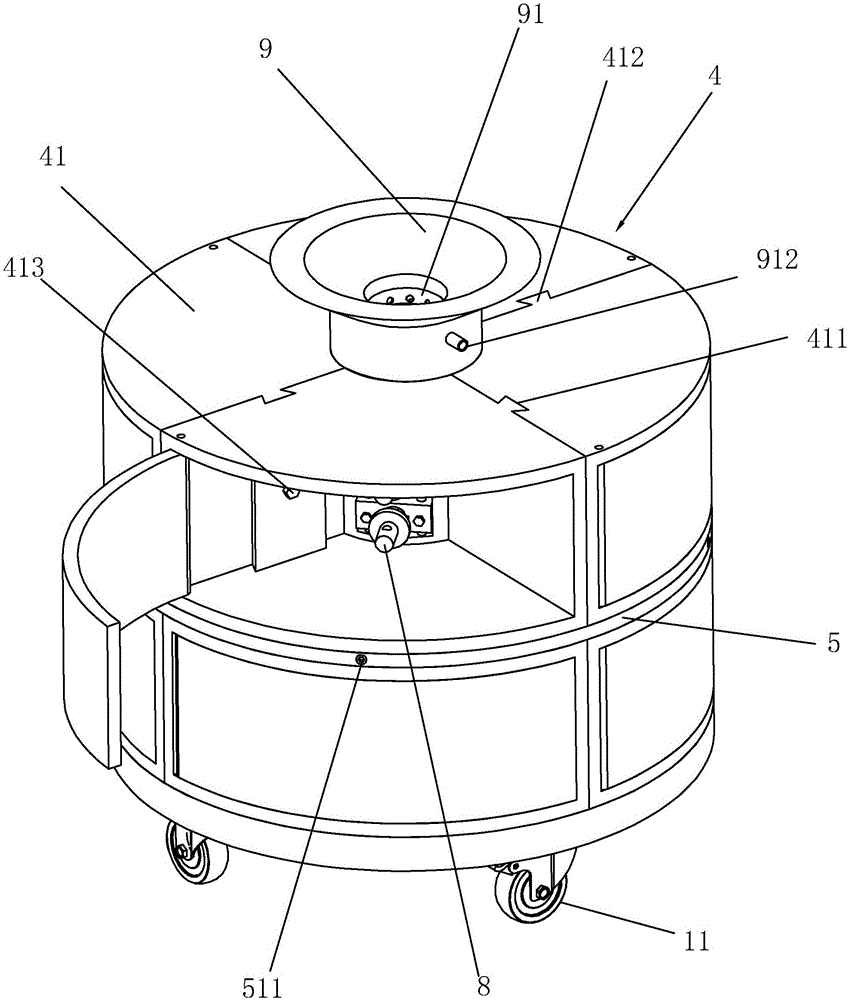
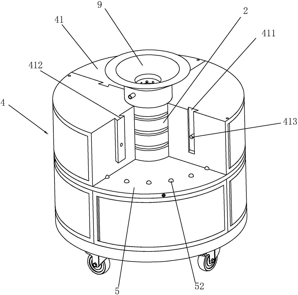
[0038] A kind of switchgear, refer to figure 1 as well as figure 2 , comprising a base 1 placed on the ground, the bottom of the base 1 is provided with a universal wheel 11, on the base 1 perpendicular to the base 1 is provided with a collection post 2, the collection post 2 is hollow, and the collection post 2 consists of several The conductive cylinders 21 are connected head to tail, and the adjacent conductive cylinders 21 are threadedly connected. The outer wall of the bottom of the conductive cylinder 21 is provided with external threads, and the inner wall of the top of the conductive cylinder 21 is provided with an internal thread that matches the external thread at the bottom of the conductive cylinder 21. thread.

[0039] refer to Figure 6 , an annular groove 3 is arranged on the outer surface of the wire gathering column 2, and there are sever...


PUM


Abstract

The invention discloses a switch cabinet. The switch cabinet is characterized in that the switch cabinet comprises a base, a wire-collecting column is located at the center on the base, the wire-collecting column is hollow, the base is provided with a distribution box, the wire-collecting column is sleeved by the distribution box and is detachably connected with the distribution box, the wire-collecting column is provided with a plurality of conducting rings in an array manner along the length direction of the wire-collecting column, the conducting rings are provided with first terminals extending to the inside of the wire-collecting column, and an inner wall of the distribution box is provided with second terminals contacted with the conducting rings. When the adding of an electric appliance element is wanted, the added wire is connected to the free first terminal in the wire-collecting column, the added electric appliance element is arranged in the distribution box, and the added electric appliance element is connected with the free second terminal so that the installation of the added electric appliance element can be completed; and since the wires are all arranged in the wire-collecting column so that the phenomenon of the wires in a mess in the distribution box due to adding of the electric appliance element is prevented.

Description

technical field [0001] The present invention relates to a power distribution equipment, more particularly, it relates to a switchgear. Background technique [0002] The switch cabinet is a kind of electrical equipment. The outside line of the switch cabinet first enters the main control switch in the cabinet, and then enters the sub-control switch. Each branch is set according to its needs. Such as instruments, automatic controls, motor magnetic switches, various AC contactors, etc., some also have high-voltage room and low-voltage room switch cabinets, high-voltage busbars, such as power plants, etc. load shedding. [0003] The invention patent with the publication number CN105390952A provides a switch cabinet, including a cabinet body, on which a cabinet door matched with the cabinet body is provided, and the switch cabinet can automatically illuminate the interior of the cabinet body after the cabinet door is opened, which improves the The operator maintains the working...

Claims


Application Information

Patent Timeline
IPC IPC(8): H02B1/30H02B1/20H01R11/11
CPCH01R11/11H02B1/202H02B1/30
Inventor 屠心磊
Owner BOGUANG ELECTRICAL TECH CO LTD
Learn More