Feeding traction device of multilayer film combining machine

A technology of traction device and composite machine, which is applied in the direction of lamination, layered products, thin material processing, etc., can solve the problems such as difficult stretching, achieve the effect of improving the pass rate, avoiding the deterioration of stretching effect, and solving the effect of upper wrinkles

Inactive Publication Date: 2017-06-09
JIANGSU YUANHUA LIGHT CHEM EQUIP
View PDF0 Cites 3 Cited by
  • Summary
  • Abstract
  • Description
  • Claims
  • Application Information

AI Technical Summary

Problems solved by technology

[0003] In view of the above existing problems, the purpose of the present invention is to provide a distribution effect for the raw material film at the feed end of the multi-layer film laminating machine, to solve the problem that the raw material film has some wrinkles that are not easy to stretch during the transmission process, and to facilitate the operation. Feeding traction device of laminating machine

Method used


Image

  • Feeding traction device of multilayer film combining machine
  • Feeding traction device of multilayer film combining machine

Examples


Embodiment 1

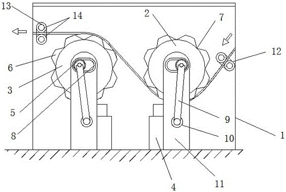
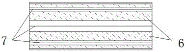
[0014] Embodiment 1: as figure 1 and 2 The feed traction device of a kind of multilayer film compound machine shown, described feed traction device is installed on the feed end of multilayer film compound machine, described feed traction device comprises fixed support 1, front traction roller 2. The rear traction roller 3 and the transmission motor 4. The front traction roller 2 is installed on the side of the rear traction roller 3. The front traction roller and the rear traction roller 3 are two identical roller bodies, and the middle part of the roller body is provided with a roller shaft 5. A plurality of protruding strip-shaped traction belts 6 are evenly distributed on the outer surface of the roller body. A V-shaped stretching groove 7 is arranged between two adjacent traction belts 6. The upper surface of the traction belt 6 is The upper surface of the arc, the roller body is fixedly installed on the ground through the support columns 11 at both ends, and the upper pa...

Embodiment 2

[0015] Embodiment 2: as figure 1 and 2 As shown, the end of the roller shaft 5 is provided with a horizontal position adjustment rod 9, and the bottom of the horizontal position adjustment rod 9 is fixedly connected to the adjustment shaft 10, and the adjustment shaft 10 is connected to the transmission motor 4; The horizontal position adjustment lever 10 is rotated, and then the roller shaft 5 is driven to move horizontally in the horizontal chute 8, and finally the gap between the front traction roller 2 and the rear traction roller 3 is changed, so that the front traction roller 2 and the rear traction roller 3 are conveniently moved. The raw film between 3 is stretched or pulled, and finally solves the problem of wrinkles on the raw film, and facilitates the uniform distribution of the raw film.

Embodiment 3

[0016] Embodiment 3: as figure 1 and 2 As shown, two sets of positioning rollers on the fixed bracket 1: the feeding positioning roller 12 and the discharging positioning roller 13, the feeding positioning roller 12 is arranged on the feeding end of the front traction roller 2, and the discharging positioning roller 13 is arranged on the rear traction roller 3. The discharge end; 12 or 13 positioning rollers are used to determine the feeding position and discharging position of the device, so as to avoid the deterioration of the stretching effect of the device on the raw material film due to changes in the feeding and discharging directions.


PUM


Abstract

The invention discloses a feeding traction device of a multi-layer film composite machine, which comprises a fixed bracket, a front traction roller, a rear traction roller and a drive motor, the front traction roller is installed on the side of the rear traction roller, the front traction roller and the rear traction roller The rollers are two identical roller bodies, the middle part of the roller body is provided with a roller shaft, and there are many protruding strip-shaped traction belts evenly distributed on the outer surface of the roller body, and V The upper surface of the traction belt is an arc-shaped upper surface. The roller body is fixed on the ground through the support columns at both ends. The upper part of the support column is provided with a horizontal chute. In the chute; the present invention stretches the raw material film when transporting the raw material film through the special outer surface structure of the roller; through the combination of the front traction roller and the rear traction roller, the raw material film is converted between the two traction rollers , to further improve the stretching effect of the raw material film, solve the problem of wrinkles on the raw material film, and facilitate the uniform distribution of the raw material film.

Description

technical field [0001] The invention relates to auxiliary equipment of a multilayer film compound machine, in particular to a feeding traction device of a multilayer film compound machine. Background technique [0002] The multi-layer film lamination machine is a device that presses a variety of films of different materials into a composite film. In order to ensure the uniform lamination effect between the multi-layer films during the lamination process, each raw material film must be maintained during the transmission process. Flat; but because the raw material film purchased on the market has certain wrinkles, and when the raw material film is transported between the rollers of the multi-layer film lamination machine, it is easy to produce certain ripples and then certain wrinkles; these formed wrinkles Before entering the pressing equipment of the film laminating machine, it needs to be processed to avoid pressing multiple layers of single-material films at the same posit...

Claims


Application Information

Patent Timeline
Patent Type & Authority Applications(China)
IPC IPC(8): B32B38/18B65H23/26B65H27/00
CPCB32B38/1825B65H23/26B65H27/00
Inventor 郭宏兵徐炜陈立云史高勤
Owner JIANGSU YUANHUA LIGHT CHEM EQUIP
Why Eureka
Try Eureka