Eureka AIR delivers breakthrough ideas for toughest innovation challenges, trusted by R&D personnel around the world.

Pipe string and completion method

A pipe string and tubing technology, which is applied in the field of oilfield development, can solve problems such as low work efficiency, and achieve the effect of improving work efficiency and saving operation time.

Inactive Publication Date: 2017-06-09
PETROCHINA CO LTD
View PDF11 Cites 4 Cited by
  • Summary
  • Abstract
  • Description
  • Claims
  • Application Information

AI Technical Summary

Problems solved by technology

[0005] The present invention provides a pipe string and well completion method to overcome the defects of low work efficiency caused by the need for two trips of drilling to realize the acid fracturing or acidizing transformation function, gas lift function and well completion function in the prior art.

Method used


Image

  • Pipe string and completion method
  • Pipe string and completion method
  • Pipe string and completion method

Examples


Embodiment 1

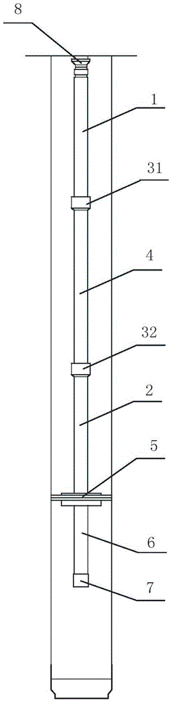
[0054] figure 1 It is a schematic structural diagram of Embodiment 1 of the column provided by the present invention. Refer to attached figure 1 As shown, this embodiment provides a pipe string, and the pipe string in this embodiment can be applied to oil testing and completion operations in Silurian sandstone reservoir blocks.

[0055] A tubing string, including a first oil pipe 1, a second oil pipe 2, a packer 5, and a third oil pipe 6 arranged from top to bottom, and the first oil pipe 1 and the second oil pipe 2 are provided with Gas lift valve.

[0056] Wherein, the first oil pipe 1 is located in the casing in the oil well. The packer 5 is used for setting at the bottom end of the casing section in the oil well. The gas lift valve is openable under gas pressure in the annulus region of the casing section in the oil well to allow gas to enter the gas lift valve from the side of the gas lift valve.

[0057] There are at least two gas lift valves, which are spaced up an...

Embodiment 2

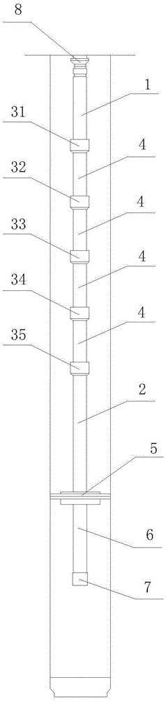
[0072] figure 2 It is a schematic structural diagram of the second embodiment of the column provided by the present invention. Refer to attached figure 2 As shown, the difference between this embodiment and Embodiment 1 is that there are five gas lift valves in this embodiment, which are the primary gas lift valve 31, the secondary gas lift valve 32, the Three-stage gas lift valve 33 , four-stage gas lift valve 34 and five-stage gas lift valve 35 .

[0073] Adjacent gas lift valves are communicated through a fourth oil pipe 4, and there are four fourth oil pipes 4 in this embodiment. Specifically, the top of the primary gas lift valve 31 communicates with the bottom end of the first oil pipe 1, and the bottom end of the primary gas lift valve 31 communicates with the top end of the secondary gas lift valve 32 through a fourth oil pipe 4. The bottom end of the stage gas lift valve 32 communicates with the top of the three stage gas lift valve 33 through a fourth oil pipe 4...

Embodiment 3

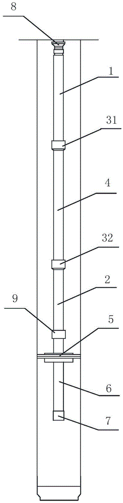
[0078] During the acid fracturing or acidizing process and subsequent oil recovery process, due to the influence of temperature changes and tubing swelling, the second tubing will be stretched or shortened due to force, and because the second tubing is connected to the packer, it is easy to cause isolation The setting seal of the device is not tight enough, and even causes abnormal unsealing, which leads to job failure.

[0079] Therefore, in order to solve the above problems, on the basis of any of the above embodiments, this embodiment provides a pipe string, referring to the attached image 3 as shown, image 3 Schematic diagram of the structure of the pipe string provided in this embodiment.

[0080] The difference between this embodiment and the above-mentioned embodiments is that a telescopic pipe 9 is added in the middle of the second oil pipe 2 .

[0081] That is, a telescopic tube 9 is connected between the top end and the bottom end of the second oil pipe 2 , and t...


PUM


Abstract

The invention provides a pipe string and a completion method. The pipe string comprises a first oil pipe, a second oil pipe, a packer and a third oil pipe which are arranged from the upper part to the lower part, wherein at least two gas lift valves are arranged between the first oil pipe and the second oil pipe; the first oil pipe is positioned in a sleeve in an oil well; each gas lift valve can be opened through pressure of gas in an annular area of a sleeve section in the oil well, and can ensure that the gas enters into the gas lift valve from the side part of the gas lift valve; the gas lift valves are longitudinally arranged at intervals; adjacent gas lift valves are communicated with each other through a fourth oil pipe; the bottom end of the first oil pipe is communicated with the top end of the gas lift valve positioned at the uppermost part; the bottom end of the gas lift valve positioned at the lowermost part is communicated with the top end of the packer through the second oil pipe. Compared with the prior art in which an acid fracturing or acidizing transformation function, a gas lift function and a completion function can be realized through two drilling, the pipe string and the completion method can realize the acid fracturing or acidizing transformation function, the gas lift function and the completion function by drilling the pipe string once, save the working duration, and improve the working efficiency.

Description

technical field [0001] The invention relates to the technical field of oilfield development, in particular to a pipe string and a well completion method. Background technique [0002] In the process of oilfield development, well completion is required. Well completion is not only the last process of drilling engineering, but also the beginning of oil production engineering. It plays an important role in linking drilling engineering and oil production engineering. In the process of well completion, acid fracturing or acidizing technology is usually required to increase the permeability of the formation, thereby increasing the oil production, and then the completion string is run to prepare for oil recovery. [0003] Generally, the casing perforation completion method is adopted in the completion of well testing in Silurian sandstone reservoir blocks. The process of well completion operation is: run acid fracturing or acidizing string into the well, inject the acid liquid int...

Claims


Application Information

Patent Timeline
IPC IPC(8): E21B43/22
CPCE21B43/16
Inventor 周建平张雪松季晓红李元斌张浩郭道忠
Owner PETROCHINA CO LTD
Why Eureka
Eureka Blog
Learn More