
Locating pin

A positioning pin and pin body technology, applied in the field of positioning parts, can solve the problems of easy bumping, poor positioning quality, instability and so on

Inactive Publication Date: 2017-06-09
CHONGQING TSINGSHAN IND
View PDF8 Cites 1 Cited by
  • Summary
  • Abstract
  • Description
  • Claims
  • Application Information

AI Technical Summary

Problems solved by technology

When this positioning pin is used in the following two situations, there is a technical problem that it is easy to damage the surface of the relevant parts and its positioning hole;
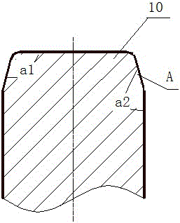
[0003] The first is to connect the bottom of the dowel pin to the top of a larger, heavier component and then lift the part to attach the top of the dowel pin to another larger, heavier component. When the positioning hole on the bottom of the pin is connected to realize positioning, if the operating space is small, the top of the pin body 10 made of metal material and the connection between the top of the pin body 10 and the guide part A and the pin body 10 and the guide part A are formed. The sharp corner a1 and the lower sharp corner a2 are easy to bump or scratch the positioning hole and the bottom surface thereof on the bottom of this other larger, heavier part, thereby causing poor and unstable positioning quality, and then reducing the other. The use effect and life of a large and heavy component
[0004] The second case is when the positioning pin is turned upside down, that is, its figure 1 After attaching the bottom of the dowel to the bottom of a larger, heavier part with the top down and the bottom up, as shown in When the positioning hole on the top of the heavier part is connected to realize positioning, if the operating space is small, the top of the pin body 10 made of metal material and the connection between the top and the guide part A and the pin body 10 and the guide part A The upper sharp angle a1 and the lower sharp angle a2 formed in the place are also easy to bruise or scratch the positioning hole and its top surface on the top of another larger and heavier component.

Method used


Image

  • Locating pin
  • Locating pin

Examples


Embodiment Construction

[0017] Preferred embodiments of the present invention will be described in detail below in conjunction with the accompanying drawings.

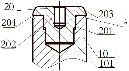
[0018] see figure 2 , The positioning pin of the present invention includes a pin body 10 made of metal material, and on the top of the pin body 10 is provided a guide portion A that is narrow at the top and wide at the bottom. Depend on figure 2 It can be seen that the present invention also includes a protective body 20 made of a softer elastic material. The protective body 20 includes a connecting portion 201 and extends radially outward from the top of the connecting portion 201 and has a maximum outer diameter smaller than or equal to the pin body. The maximum outer diameter of 10, the protective portion 204 whose lower surface fits the top of the pin body 10, the top of the pin body 10 is provided with a connecting blind hole 101 extending longitudinally downward, the connecting portion of the protective body 20 201 is interference ...


PUM


Abstract

The invention provides a locating pin with better locating quality and relatively-high stability. The locating pin comprises a pin body (10) made of a metal material, wherein a guiding part (A) with an upper narrow part and a lower wide part is arranged on the top of the pin body (10). The locating pin is characterized by also comprising a protecting body (20) made of a softer material; the protecting body (20) comprises a connecting part (201) and a protecting part (204); the protecting part (204) radially outward extends from the top of the connecting part (201), the maximum outside diameter of the protecting part (204) is smaller than or equal to that of the pin body (10), and the lower surface of the protecting part (204) is attached to the top of the pin body (10); a connecting blind hole (101) which longitudinally downward extends is formed in the top of the pin body (10); the connecting part (201) of the protecting body (20) is in interference fit with the connecting blind hole (101) of the pin body (10).

Description

technical field [0001] The invention relates to a positioning piece in the mechanical field, in particular to a positioning pin. Background technique [0002] Those skilled in the art know that at present, the most common positioning elements in the mechanical field are positioning pins. see figure 1 and figure 2 As shown, a common positioning pin includes a pin body 10 made of metal material. On the top of the pin body 10, a guide part A with a narrow top and a wide bottom is provided. The guide part A is used in the use of the positioning pin. Guidance is carried out to facilitate the connection of the pin body 10 with the positioning holes on the relevant parts. When this positioning pin is used in the following two situations, there is a technical problem that it is easy to damage the surface of the relevant parts and its positioning hole; [0003] The first is to connect the bottom of the dowel pin to the top of a larger, heavier component and then lift the part to...

Claims


Application Information

Patent Timeline
IPC IPC(8): F16B19/02
CPCF16B19/02
Inventor 文世双雷建明王荣波陈梅刘松王国龙周江赖鹏杨鹏
Owner CHONGQING TSINGSHAN IND
Learn More