Using method of scraper stop valve

A shut-off valve and scraper technology, which is used in lift valves, valve devices, engine components, etc., can solve the problems that the sealing surface of the valve disc and the sealing surface of the valve seat cannot be tightly combined, the sealing pair is easily damaged, and the service life is short. The effect of good sealing, enhanced valve life and long service life

Active Publication Date: 2017-06-09
李祥庆
View PDF4 Cites 6 Cited by
  • Summary
  • Abstract
  • Description
  • Claims
  • Application Information

AI Technical Summary

Problems solved by technology

[0002] As an extremely important cut-off valve, the globe valve is sealed by applying torque to the valve stem, and the valve stem exerts pressure on the valve disc in the axial direction, so that the sealing surface of the valve disc and the sealing surface of the valve seat fit closely, preventing The medium leaks along the gap between the sealing surfaces. The sealing pair of the globe valve is composed of the disc sealing surface and the valve seat sealing surface. The valve stem drives the valve disc to move vertically along the center line of the valve seat. When the valve is used in viscous ore slurry containing solid particles, the medium is easy to stick to the sealing pair, so that the sealing surface of the disc and the seat cannot be tightly combined, resulting in leakage. At the same time, the solid particles contained in the medium are trapped On the sealing pair, it is easy to damage the sealing pair and the service life is short

Method used


Image

  • Using method of scraper stop valve
  • Using method of scraper stop valve
  • Using method of scraper stop valve

Examples


Embodiment Construction

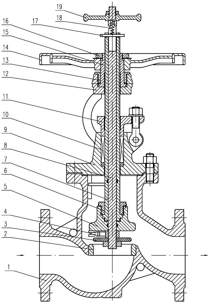
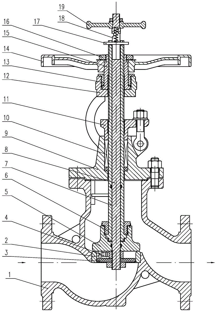
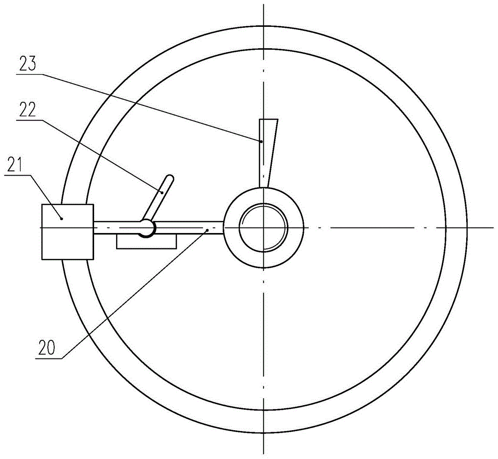
[0028] according to figure 1 , figure 2 and image 3It can be seen that a cut-off valve with a scraper in the present invention includes: a valve body 1, a valve seat 2, an outer valve stem 7, a valve disc 5 and a valve cover 9, and the valve body 1 is provided with an inlet flow channel, an outlet flow channel and a middle cavity. The outlet channel communicates with the middle cavity, the valve seat 2 is set at the outlet end of the inlet channel, the upper end of the valve seat 2 is provided with a valve seat sealing surface, the valve seat 2 is provided with an inner cavity, and the valve cover 9 is fixedly installed on the upper end of the middle part of the valve body 1, The middle part of the bonnet 9 is provided with a stuffing box, and a packing 10 and a packing gland 11 are installed at the stuffing box. The packing gland 11 presses the packing 10 downwards. There is a groove, and a valve stem nut 15 and a limit sleeve 13 are arranged at the groove, and the limit ...


PUM


Abstract

The invention relates to a using method of a scraper stop valve. The using method comprises the following steps: from an open state to a closed state, lifting a positioning pin till the two ends of the positioning pin are clamped into a concave seam allowance respectively, clockwise rotating a small hand wheel to drive an internal valve rod and a scraper assembly to rotate, outwardly moving a cutter head, and moving an upper scraper to a valve clack sealing surface; anticlockwise and outwardly rotating a big hand wheel to drive a valve clack, the scraper assembly, a plug head and other components to move downward till a lower scraper contacts a valve seat sealing surface, continuing rotating the small hand wheel for a round clockwise, then anticlockwise rotating the small hand wheel till the head of an inclined rod contacts a baffle block, continuing rotating the small hand wheel anticlockwise to drive the cutter head to move inward, moving the upper scraper and the lower scraper away from the valve clack sealing surface and the valve seat sealing surface respectively, and stopping rotating the small hand wheel; moving the positioning pin away from the concave seam allowance, moving downwardly, and clamping the two ends of the positioning pin into a clamping slot; continuing rotating the big hand wheel anticlockwise till the valve clack sealing surface presses against the valve seat sealing surface, and closing the valve. The using method of the scraper stop valve is simple; by the using method, wear of sealing surfaces is low and the service life of the scraper stop valve is prolonged.

Description

technical field [0001] The invention relates to a cut-off valve, in particular to a method for using a cut-off valve with a scraper. Background technique [0002] As an extremely important cut-off valve, the globe valve is sealed by applying torque to the valve stem, and the valve stem exerts pressure on the valve disc in the axial direction, so that the sealing surface of the valve disc and the sealing surface of the valve seat fit closely, preventing The medium leaks along the gap between the sealing surfaces. The sealing pair of the globe valve is composed of the disc sealing surface and the valve seat sealing surface. The valve stem drives the valve disc to move vertically along the center line of the valve seat. When the valve is used in viscous ore slurry containing solid particles, the medium is easy to stick to the sealing pair, so that the sealing surface of the valve disc and the seat sealing surface cannot be tightly combined, resulting in leakage, and the solid p...

Claims


Application Information

Patent Timeline
Patent Type & Authority Applications(China)
IPC IPC(8): F16K1/32F16K1/36F16K1/00
CPCF16K1/00F16K1/32F16K1/36
Inventor 李祥庆
Owner 李祥庆
Why Eureka
Try Eureka