Lamp body structure
A lamp body and lamp head technology, applied in the field of lighting, can solve problems such as promotion limitations, and achieve the effects of saving and protecting the environment, achieving sustainable development, and saving resources
- Summary
- Abstract
- Description
- Claims
- Application Information
AI Technical Summary
Problems solved by technology
Method used
Image

Examples
Embodiment 1
[0056] Please refer to Figure 1-8 , The first embodiment of the present invention is:
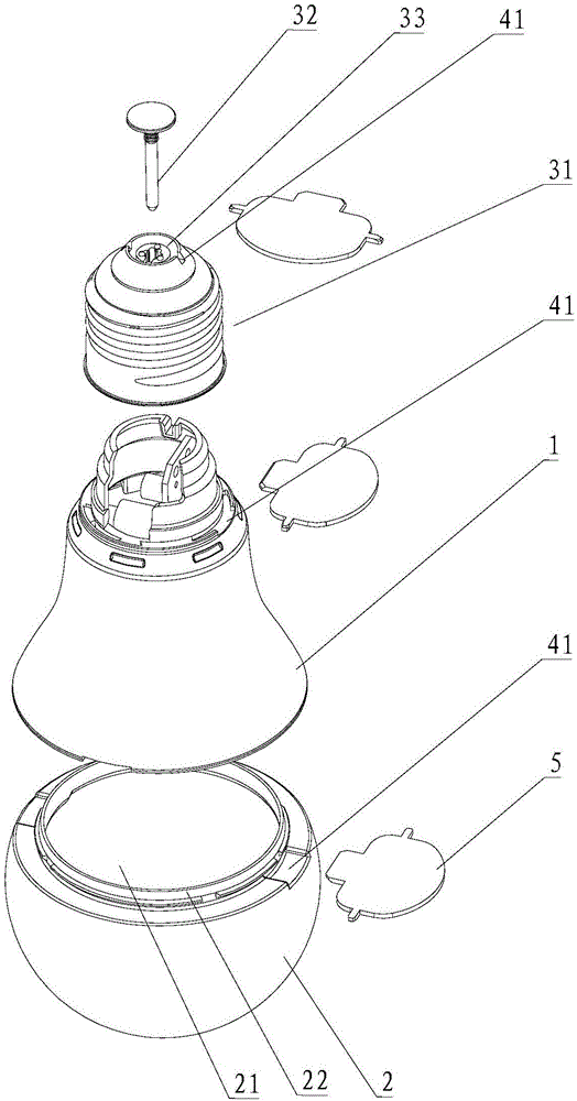
[0057] In the lamp body structure of this embodiment, the upward direction of the light emitting unit in the lamp body structure is the top direction, and the opposite direction is the bottom direction. The lamp body structure includes a lamp body 1, a lamp shade 2 and a lamp cap 3. The lamp cap 3 includes a lamp cap shell 31 and a conductive connecting piece 32. The lamp shade 2 is a cover structure with an opening 21 at the bottom, and a fixing ring 22 is provided at the bottom of the lamp shade 2 , The inner side wall of the lamp body 1 is provided with a fixing groove 11 corresponding to the fixing ring, and the fixing ring 22 is buckled in the fixing groove 11 so as to cover the top of the lamp body 1 and the bottom of the lamp body 1. Screwed with the top thread of the lamp cap housing 31 in the lamp cap 3, the bottom of the lamp cap housing 31 in the lamp cap 3 is provided with an open...
Embodiment 2
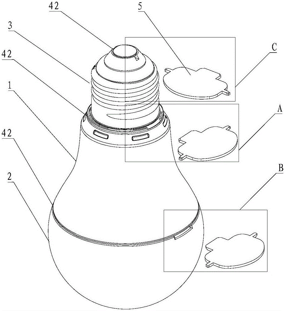
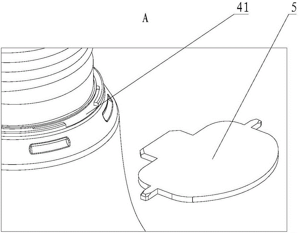
[0064] Only "wherein, the slot 41 provided at the connection between the lamp body 1 and the lamp shade 2 is all set on the top of the lamp body 1, and is connected to the outer side wall of the lamp body 1, and the slot 41 connects the lamp shade 2 and the lamp body 1 connection surface.
[0065] The slots 41 provided at the connection between the lamp body 1 and the lamp holder 3 are all arranged on the top of the lamp holder 3 and communicate with the outer side wall of the lamp holder 3, and the slot 41 communicates with the connecting surface of the lamp holder 3 and the lamp body 1.
[0066] The slots 41 provided at the connection between the lamp holder housing 31 and the conductive connector 32 are all provided on the top of the conductive connector 32 and communicate with the outer side wall of the conductive connector 32, and the slot 41 communicates with the lamp holder housing 31 The connection surface with the conductive connector 32. "Different, the others are the sa...
Embodiment 3
[0068] Only "wherein, the slot 41 provided at the connection between the lamp body 1 and the lamp shade 2 is partly set on the top of the lamp body 1 and the other portion is set on the bottom of the lamp shade 2, and the slots 41 are respectively connected to the lamp body 1. The outer side wall of the lampshade 2 is connected and arranged, and the slot 41 is connected to the connecting surface of the lampshade 2 and the lamp body 1.
[0069] The slot 41 provided at the connection between the lamp body 1 and the lamp cap 3 is partly set at the bottom of the lamp body 1 and the other part is set at the top of the lamp cap 3. The slot 41 is connected to the lamp body 1 and the lamp cap 3 respectively. The outer side wall of the lamp is communicated with, and the slot 41 communicates with the connecting surface of the lamp cap 3 and the lamp body 1.
[0070] The slot 41 provided at the connection between the lamp holder housing 31 and the conductive connector 32 is partly provided at...
PUM
 Abstract
Description
Claims
Application Information