Seat tray

A tray and seat technology, applied in chairs, other seating furniture, stools, etc., can solve the problems of unsafe use, inability to automatically adjust the rigidity of the backrest, troublesome operation, etc., and achieve a reduction in the deformation range, increase in rigidity, and simple operation. Effect

Inactive Publication Date: 2017-06-13
ZHEJIANG UNIVERSITY OF SCIENCE AND TECHNOLOGY +1
View PDF7 Cites 0 Cited by
  • Summary
  • Abstract
  • Description
  • Claims
  • Application Information

AI Technical Summary

Problems solved by technology

[0003] The purpose of the present invention is to solve the problem in the prior art that the rigidity of the backrest of the seat cannot be automatically adjusted with the change of the user's weight, resulting in unsafe use, and the need to toggle the shift fork for the backrest to return to the initial position, which is troublesome to operate, and realizes a The device that can restore the backrest angle to the initial position has a simple structure, and can automatically adjust the rigidity of the backrest according to the force of the seat cushion, which is suitable for people of different weights, and the seat tray with high comfort

Method used


Image

  • Seat tray
  • Seat tray
  • Seat tray

Examples


Embodiment 1

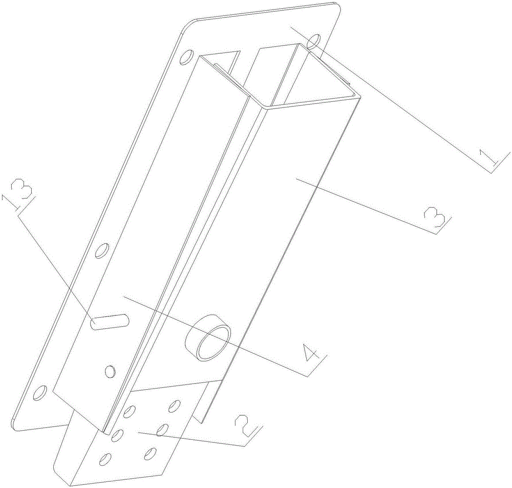
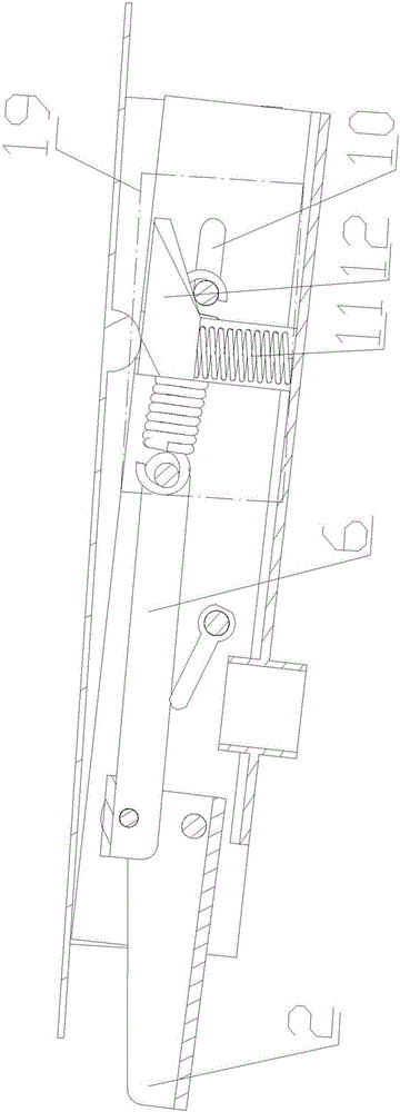
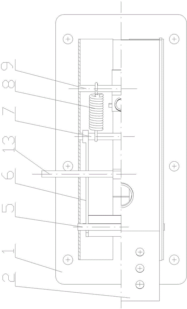
[0017] Embodiment one: if Figure 1-5 As shown, a seat tray includes a seat cushion support plate 1, a backrest connecting plate 2 and a base 3. Flanges 4 are longitudinally arranged under both sides of the seat cushion support plate 1, and there are Base 3, the base 3 is U-shaped with an opening facing upwards, one end of the backrest connecting plate 2 is rotationally connected with the base 3 through a rotating shaft 5, the base 3 is rotationally connected with the seat cushion supporting plate 1, and the backrest connecting plate 2 The end part is connected to the connector 6 in rotation, the other end of the connector 6 is provided with an automatic adjustment backrest rigidity device 19, the base 3 is provided with a lifting adjustment rod 13, and the seat cushion supporting plate 1 is provided with a sliding groove. The sliding groove is compatible with the lifting adjustment rod 13, and the connector 6 is provided with a set of limit teeth 14, and the end surface of th...

Embodiment 2

[0023] Embodiment two: if Figure 1-5 As shown, a seat tray includes a seat cushion support plate 1, a backrest connecting plate 2 and a base 3. Flanges 4 are longitudinally arranged under both sides of the seat cushion support plate 1, and there are Base 3, the base 3 is U-shaped with an opening facing upwards, one end of the backrest connecting plate 2 is rotationally connected with the base 3 through a rotating shaft 5, the base 3 is rotationally connected with the seat cushion supporting plate 1, and the backrest connecting plate 2 The end part is connected to the connector 6 in rotation, the other end of the connector 6 is provided with an automatic adjustment backrest rigidity device 19, the base 3 is provided with a lifting adjustment rod 13, and the seat cushion supporting plate 1 is provided with a sliding groove. The sliding groove is compatible with the lifting adjustment rod 13, and the connector 6 is provided with a set of limit teeth 14, and the end surface of th...


PUM


Abstract

The invention discloses a seat tray which comprises a cushion supporting plate, a backrest connecting plate and a base, wherein one end of the backrest connecting plate is rotatably connected with the base through a rotating shaft; the base is rotatably connected with the cushion supporting plate; the end of the backrest connecting plate is rotatably connected with a connector; an automatic rigid backrest adjusting device is arranged at the other end of the connector; a lifting adjustment lever is arranged on the base; a group of limiting teeth is arranged on the connector; a bevel angle telescopic head matched with the limiting teeth is arranged on the end face of the lifting adjustment lever; the limiting teeth take the telescopic direction of the bevel angle telescopic head as a baseline, the inclination of the left side face of the limiting teeth is 20-40 degrees, and the inclination of the right side face of the limiting teeth is 45-70 degrees. Both the left and right sides of the limiting teeth have a certain inclination, however, on one side with smaller inclination, the lifting adjustment lever cannot return by virtue of return force of a spring and can return by virtue of an external force. Therefore, a return device, such as a shifting fork, is avoided, and the operation is simple.

Description

technical field [0001] The invention belongs to the mechanical field of office chairs and swivel chairs, in particular to a seat tray. Background technique [0002] At present, most of the seats with backrests with tilting function are connected to the backrest through torsion springs or pressure springs, so that the backrest automatically resets after the external force is removed. For example, the Chinese patent with the publication number CN203106378 discloses a seat tray using a leaf spring, including a tray main body, a leaf spring and a back support plate. A longitudinal groove is formed on the bottom plate of the main body of the tray, and the depth gradually increases from the middle of the bottom plate to the edge. The width of the leaf spring is slightly smaller than the width of the groove. One end is installed on the bottom plate of the main body of the tray near the groove, and the other end is a free end, which can be bent downward in the groove and reset auto...

Claims


Application Information

Patent Timeline
Patent Type & Authority Applications(China)
IPC IPC(8): A47C7/44
CPCA47C7/44
Inventor 曹淼龙
Owner ZHEJIANG UNIVERSITY OF SCIENCE AND TECHNOLOGY
Why Eureka
Try Eureka